page 13
CTs 2-Channel Power Amplifiers
Operation Manual
4.2 Front Panel Controls
and Indicators
A. Fault Indicator
Red LED, one per channel, flashes when
the amplifier output channel has stopped
operating. Usually this means that the
amplifier must be serviced.
B. Thermal Indicator
Red LED, one per channel, illuminates
when the channel has shut down, or is
very near shutting down, due to thermal
stress or overload.
C. Ready Indicator
Green LED, one per channel, illuminates
when the channel is initialized and ready to
produce audio output. Indicator is off when
the channel is set to standby mode via the
IQ system.
Signal Indicators
Three green LEDS per channel indicate the
amplifier’s input and output signal levels.
From bottom to top the LEDs are:
D. Signal: input signal is above –40 dBu.
E. –20 dB: amplifier output is within 20 dB of
clipping.
F. –10 dB: amplifier output is within 10 dB of
clipping.
G. Clip Indicator
Red LED, one per channel, illuminates
when the channel’s output signal reaches
the onset of audible clipping. The Clip
Indicator also will illuminate during Ther-
mal Level Control (TLC) limiting or when
the input compressor/limiter is protecting
the amplifier from input overload.
H. Cooling Vents
Front-to-rear forced airflow.
I. Power Indicator
Blue LED indicates AC power has been
applied and is within the safe operating
range of the power supply. The LED will
flash when the AC line voltage is approxi-
mately 15% above or 25% below the nom-
inal rated value.
J. Data Indicator
Yellow LED indicates IQ Loop data activity
This LED is driven by the IQ-PIP2 module
via the PIP2
interface. Note: Data indicator
flashes only when the installed PIP module
is polled for data, or is polled to see
whether it is online.
K. Bridge Mode Indicator
Yellow LED illuminates when the rear-
panel Mode Switch is set to the “Bridge”
position
L. Power Switch
Push-on / push-off switch.
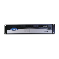
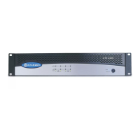
Figure 4.1 CTs 600 front panel.
4 Operation