2–7
Installation
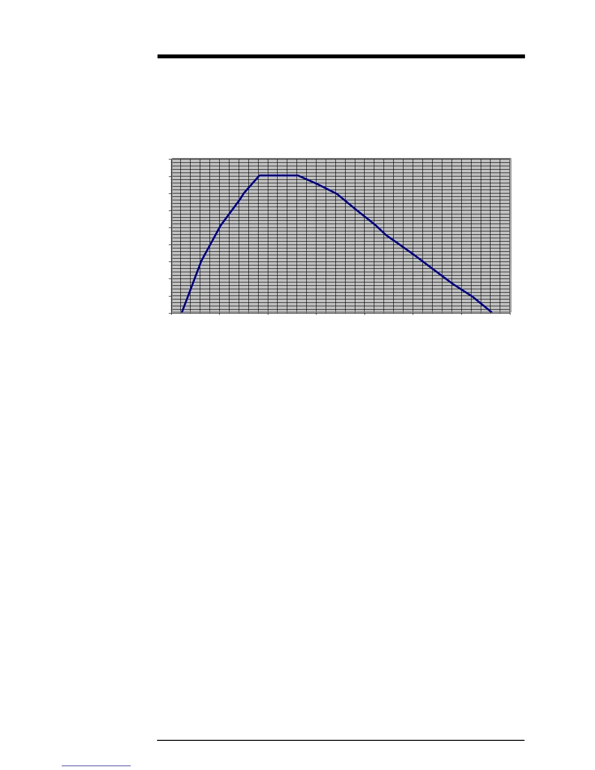
2.3.1 Modulation Compensator
The Modulation trim-potentiometer (see illustration 2–6) compensates for slight
variations in deviation sensitivity with frequency. Set the trim-pot dial according to
the following graph:
Illustration 2–9 Modulation Compensator Settings
These compensator settings are approximate. Each mark on the potentiometer
represents about 1.8% modulation compensation. For more exact settings, refer to
section 5.2.2.
Modulation Compensation Pot Setting
0
10
20
30
40
50
60
70
80
90
75 80 85 90 95 100 105 110
Frequency (MHz)