Now put the amplifier boards back into the chassis. Fit the minimum of screws to ensure good earthing. If there are any
further problems, it is very frustrating to have to undo all the fixing screws again.
The screw fixings we suggest are
z The two chassis earth points.
z One of each heat sink to chassis screw.
z One silver PCB to chassis screw.
z Two output panel screws.
This will allow you to run the amplifier and perform the quick test. You will use a large input signal and overdrive each
channel for a while, then short the output and again overdrive each channel for a while.
1. Load the output to 4 ohms.
2. Turn the level control to maximum.
3. Inject a +5 dBu, 100Hz sine wave signal into each channel's input and check for heavily clipped output. Run for 30
seconds.
4. After 30 seconds, short circuit the output for a further 30 seconds.
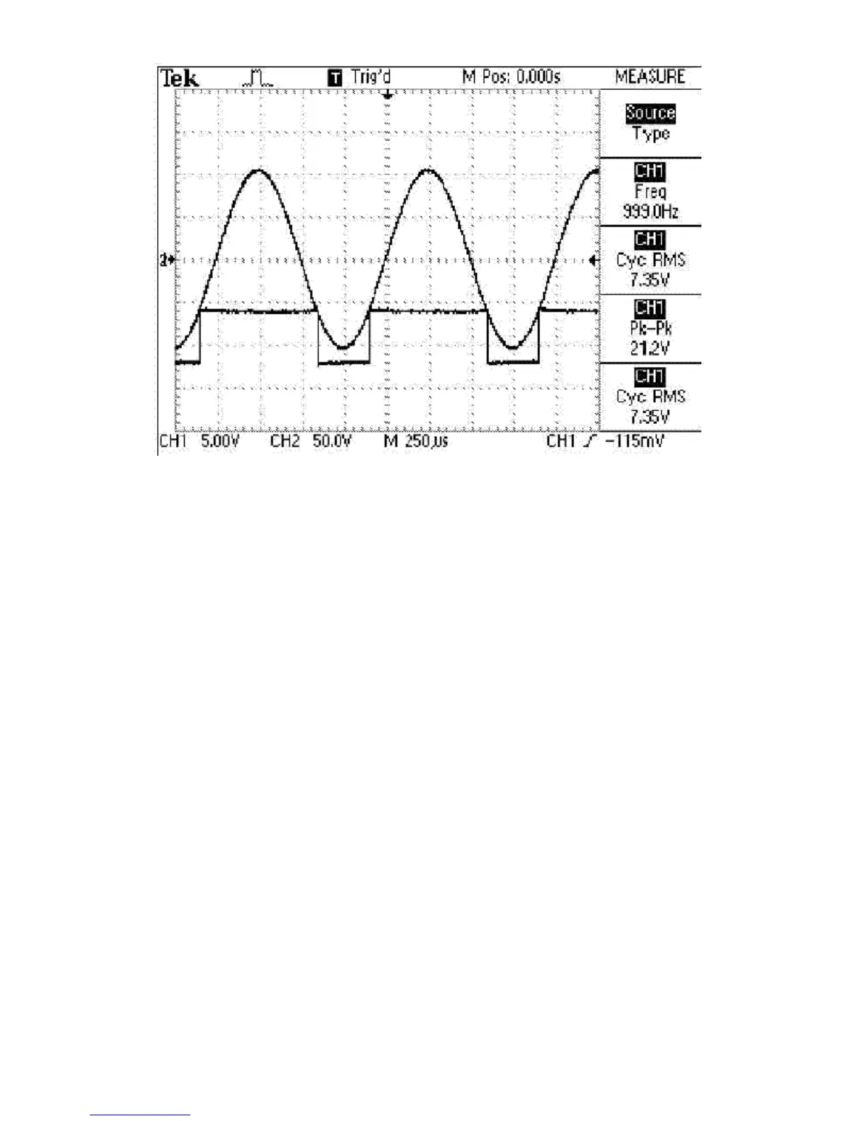
5. Remove the short circuit and reduce the signal to +1.5 dBu (+1 dBu for the 4x300). You should see a clean, unclipped
output at the correct level shown below.
z
4x300
300W
z
2x650
650W
z
2x1100
1100W
3 Checkout/Adjustment Procedures
The following instructions outline an orderly checkout and troubleshooting procedure. The purpose and arrangement of this
procedure is to ensure proper operation after a repair has been completed. Before beginning these power-on tests, perform
 Loading...