Home
CSI Wireless
Receiver
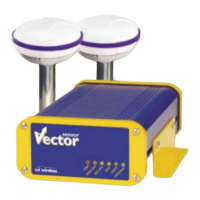
Vector Sensor
CSI Wireless Vector Sensor - User Manual
145 pages
Manual
Specs
Ask a question
Save Page as PDF
To Next Page
To Next Page
Loading...
Vector Sensor
Reference Manual
Part Number
875
-
0075
-
001
Date:
March
2004
2
Table of Contents
Main Page
Table of Contents
5
List of Figures
11
Preface
14
Organization
15
Customer Service
15
World Wide Web Site
16
Document Conventions
16
Notes, Cautions, and Warnings
16
Quick Start
17
Receiving Your Shipment
17
Unpacking Your Vector Sensor System
17
Cable Connections
18
Understanding the Vector Sensor
18
Figure 1-1 Cable Interface
18
Moving Base Station RTK
19
Supplemental Sensors - Reduced Search Time
19
Supplemental Sensors - Heading System Backup
19
Installation Overview
20
Mounting Configurations and Offset Settings
21
Gyro Initialization Process
21
NMEA 0183 Message Interface
22
Tilt Aiding
22
Tilt Sensor Calibration
22
Magnetic Aiding
22
Magnetometer Calibration
23
Gyro Aiding
24
Time Constants
25
Level Operation
28
Heading Compensation
28
Configuring for Pitch or Roll
29
Configuring Negative Pitch or Roll
29
Pitch / Roll Compensation
30
Forcing a New RTK Search
31
Antenna Separation
31
Summary Command
32
HELP Command
32
HEHDT Message
33
HEROT Message
33
Proprietary $PSAT,INTLT Message
33
Proprietary $PSAT,HPR Message
34
Installation
35
System Parts List
35
Cable Interface
35
Figure 2-1 Cable Interface
35
Vector Antenna Array Placement
36
Placement and Beacon Reception
36
Environmental Considerations
37
Power Considerations
37
Electrical Isolation
37
Vector Antenna Array Mounting
37
Table 2-1 Power Requirements
37
Magnetic Mounting (Optional Accessory)
38
Pole and Rail Mounting
38
Routing and Securing the Antenna Cable
39
Connecting the CDA-RTK and MBL-3 Antennas
40
Powering the Vector Sensor
40
Turning the Vector Sensor on
41
Connecting the Vector Sensor to External Devices
41
Table 2-2 Port a Pin-Out, RS-232C Interface Level
41
Table 2-3 Port B Pin-Out, RS-232C Interface Level
41
Figure 2-2 DB9 Socket Numbering
42
Figure 2-3 Port a Interface
42
Table 2-4 Display Only Pin-Out, RS-232C Interface
42
LED Indicators
43
Figure 2-4 Port B Interface
43
Table 2-5 LED Indicator Definition
43
Figure 2-5 Vector Sensor Evaluation Front Panel
44
Overview
45
Gps
45
Satellite Tracking
45
Positioning Accuracy
45
Update Rates
46
Sbas
46
Automatic Tracking
46
SBAS Performance
46
Beacon Operation
47
Tune Modes
47
Receiver Performance
49
Table 3-1 Beacon Receiver Performance - SNR Reading
49
COAST™ Technology
50
Default Parameters
50
Table 3-2 Firmware Applications
50
Table 3-3 Default Port Settings
50
Table 3-4 Default GPS NMEA Message Output
50
Table 3-5 Correction Age and Elevation Mask Defaults
50
Vector Sensor Architecture
52
GPS Hardware
52
GPS Firmware
52
GPS Applications
52
Table 3-6 Beacon Operating Parameters
52
Table 3-7 Default Differential Mode
52
Beacon Firmware
53
Operation
54
Powering the Vector Sensor
54
Communicating with the Vector Sensor
54
NMEA 0183 Interface
54
Binary Interface
55
RTCM SC-104 Protocol
55
Configuring the Vector Sensor
56
Configuring the Data Message Output
56
This Port and the Other Port
57
Pocketmax Utility
58
NMEA 0183 Messages
60
NMEA Message Elements
60
Pocketmax
60
Table6-1 NMEA Message Elements
60
General Commands
61
Figure 6-1 Pocketmax Screen Capture
61
Jasc,D1
62
Table 6-2 General Commands
62
Jair
63
Jasc,Virtual
63
Jalt
64
Jlimit
65
Japp
65
Jbaud
66
Jconn
66
Jdiff
67
Jpos
68
Jquery,Guide
68
Jreset
69
Jsave
69
Jshow
69
Jbin
72
GPS Commands
72
Jasc
73
Table 6-3 GPS Commands
73
Jage,Age
74
Joff
74
Jmask
74
J4String
75
Jsmooth
75
SBAS Commands
76
Jwaasprn
76
Table 6-4 SBAS Commands
76
Jgeo
77
Jasc,D1
78
Jasc,Rtcm
78
Data Messages
79
Table 6-5 Data Messages
79
GGA Data Message
80
GLL Data Message
80
Table 6-6 GGA Data Message Defined
80
Table 6-7 GLL Data Message Defined
80
GSA Data Message
81
GST Data Message
81
Table 6-8 GSA Data Message Defined
81
Table 6-9 GSA Data Message Defined
81
GSV Data Message
82
RMC Data Message
82
Table 6-10 GSV Data Message Defined
82
Table 6-11 RMC Data Message Defined
82
RRE Data Message
83
VTG Data Message
83
Table 6-12 RMC Data Message Defined
83
Table 6-13 VTG Data Message Defined
83
ZDA Data Message
84
RD1 Data Message
84
Table 6-14 ZDA Data Message Defined
84
Table 6-15 RD1 Data Message Defined
84
PCSI,1 Beacon Status Message
86
HDT Data Message
87
ROT Data Message
87
HPR Data Message
87
Beacon Receiver Commands
87
Table 6-16 SBX Beacon Commands
87
GPMSK Beacon Tune Command
88
PCSI,1 Beacon Status Command
88
GPS Heading Commands
89
Jatt,Tiltaid
90
Table 6-17 GPS Heading Commands
90
Jatt,Tiltcal
91
Jatt,Magaid
91
Jatt,Magcal
91
Jatt,Magclr
92
Jatt,Gyroaid
93
Jatt,Level
93
Jatt,Csep
94
Jatt,Msep
94
Jatt,Htau
94
Jatt,Ptau
95
Jatt,Hrtau
95
Jatt,Cogtau
96
Jatt,Spdtau
97
Jatt,Hbias
97
Jatt,Pbias
98
Jatt,Negtilt
98
Jatt,Roll
98
Jatt,Search
99
Jatt,Flipbrd
99
Jatt,Summary
99
Jatt,Help
101
Binary Data
102
Binary Message Structure
102
Bin 1
102
Bin 2
102
Table 7-1 Binary Message Structure
102
Bin 80
103
Bin 93
103
Table 7-2 bin 1 Message
103
Table 7-3 bin 2 Message
103
Bin 94
104
Table 7-4 bin 80 Message
104
Bin 95
105
Table 7-5 bin 93 Message
105
Bin 96
106
Bin 97
106
Table 7-6 bin 94 Message
106
Table 7-7 bin 95 Message
106
Bin 98
107
Table 7-8 bin 96 Message
107
Table 7-9 bin 97 Message
108
Table 7-10 bin 98 Message
108
Bin 99
109
Table 7-11 bin 99 Message
109
Frequently Asked Questions
111
Heading
111
General
111
Support and Repairs
112
Troubleshooting
112
Power, Communication, and Configuration
113
GPS Reception and Performance
114
SBAS Reception and Performance
114
Beacon Reception and Performance
115
External Corrections
116
Installation
116
Troubleshooting
117
Table 9-1 Troubleshooting
117
Appendix A - Specifications
119
Table A-1 Specifications
119
Table A-2 Vector Antenna Array Specifications
120
Table A-3 MBL-3 Specifications
120
Appendix B - Interface
122
Figure B-1 GPS Data Interface
122
Figure B-2 RTCM Data Output Interface
123
Appendix C - Introduction to GPS and SBAS
125
Figure C-1 WAAS Coverage
135
Figure C-2 EGNOS Coverage
136
Figure C-3 Broadcast WAAS Inonspheric Correction Map
137
Figure C-4 Extrapolated WAAS Inonspheric Correction Map
138
Figure C-5 Broadcast EGNOS Inonspheric Correction Map
138
Figure C-6 Extrapolated EGNOS Inonspheric Correction Map
138
Figure C-7 World DGPS Radiobeacon Coverage
140
Appendix D - Resources
142
Index
144
Other manuals for CSI Wireless Vector Sensor
Programming Manual
136 pages
Need help?
Do you have a question about the CSI Wireless Vector Sensor and is the answer not in the manual?
Ask a question
CSI Wireless Vector Sensor Specifications
Print Specification
General
Operating Temperature
-40°C to +85°C
Frequency Range
902-928 MHz
Antenna
omnidirectional
Interface
RS-232
RF Channels
50 channels
Related product manuals
CSI Wireless DGPS MAX
136 pages