APPENDIX 2
Input Connections
There are 8 input terminals on the DualCom (16 with the CS1050 Expander).
When DualCom is triggered the voltages on the input terminals are 0 volts
changing to a positive voltage, (normally +4 volts to +12 volts), or they may be
a positive voltage changing to 0 volts. This is called ‘positive applied’ or ‘positive
removed’ triggering.
The Inputs may be programmed to send an alarm call when a positive voltage is
applied to an input or when a positive voltage is removed. See the CS0054
NVM Programmer Manual for details.
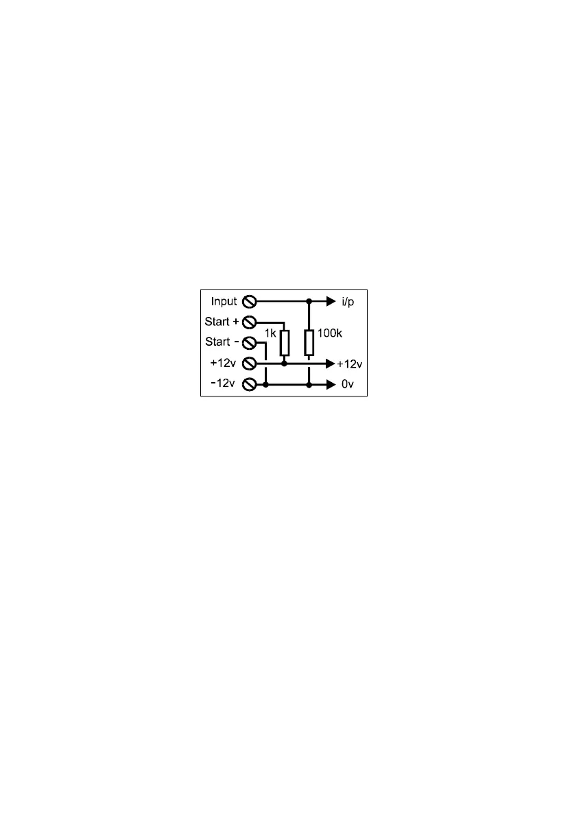
The figure above shows the internal connections of the DualCom inputs.
The +12 volt and 0v supply from the Control Panel or Power Supply is con-
nected to the +12v & - 12v terminals.
Each of the input terminals on DualCom is connected to 0 volts by a resistor.
Therefore, by leaving an input terminal unconnected this will ensure that that
the input is connected to 0 volts.
The ‘Start+’ terminal on DualCom is an output. It will give a positive’pull-up’
voltage which can be used to assist input triggering.
The ‘Start-’ terminal is hard connected to 0 volts and can be used to assist input
triggering.
DualCom internal connections
39
 Loading...