40
APPENDIX 2
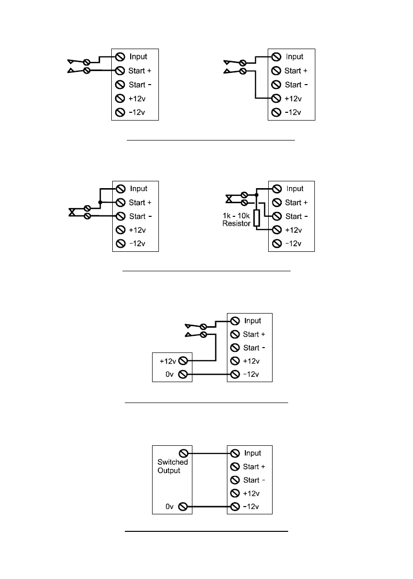
Input Connections (continued)
Examples of ‘Positive Applied’ triggering
Contact is ‘Normally Open’. Input is normally at 0 volts.
When contact closes the input becomes +12 volts.
Examples of ‘Positive Applied’ triggering
Contact is ‘Normally Closed’. Input is normally at 0 volts.
When contact opens the input becomes +12 volts.
Power
Supply
Example of ‘Positive Applied’ triggering
Contact is ‘Normally Open’. Input is normally at 0 volts.
When contact closes the input becomes +12 volts.
Example of ‘Positive Applied’ triggering
Control Panel Switched Output is 0 volts changing to a positive voltage
Control
Panel
 Loading...