Emizon TCD
Step 3 - Connecting Relays
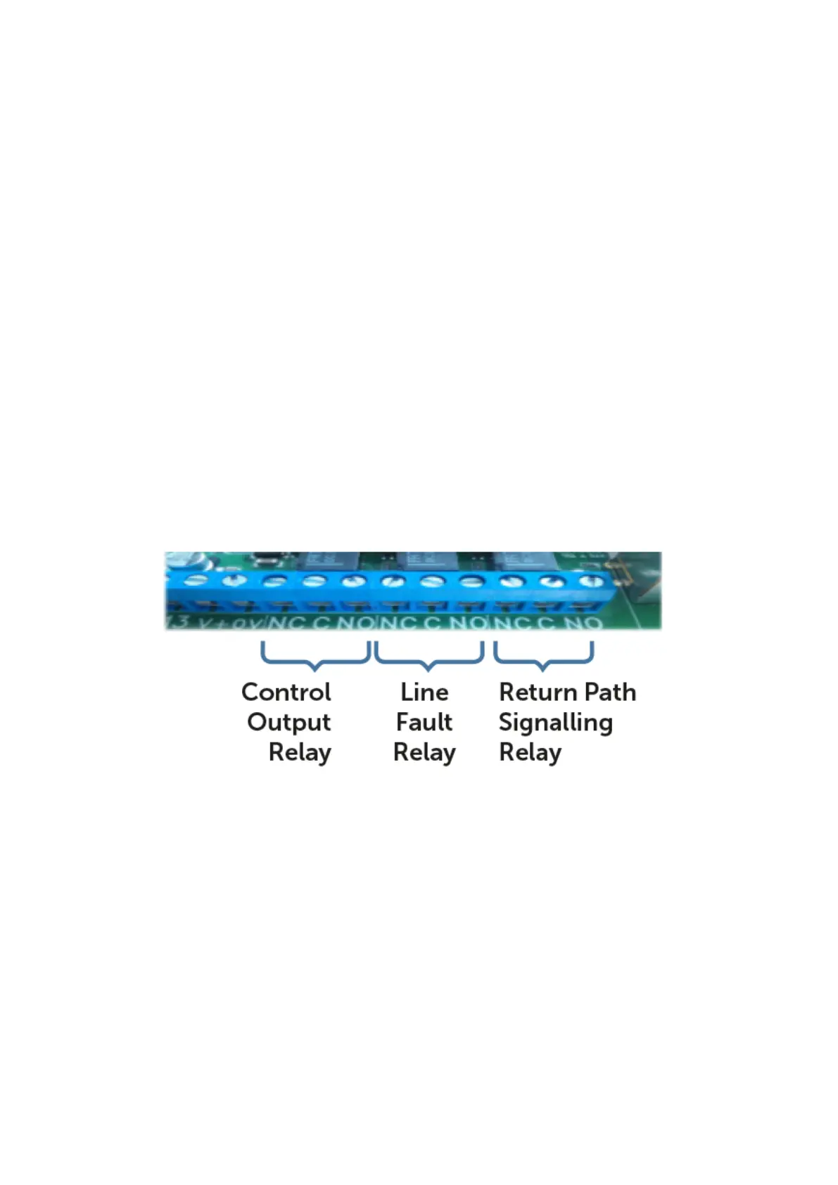
The three changeover relays are rated at 30 Volts DC @ 1A. All 3 relays are Non-
Latching. The line fault relay will be in the N/O position when there is no line fault
and fall back the N/C position when there is a line fault or other fault which would
prevent the TCD from operating normally. The Line Fault relay can therefore be used
as a fault output, signalling N/C to indicate a fault condition. Note: The Relays can be
configured in a number of combinations via Online Maintenance Software.
Control Output - Controlled by the ARC and used for various purposes such as re-
setting the alarm panel following an event.
Line Fault - N/C when the TCD is in line fault. This relay is defaulted to operate in
BSIA Form 175 mode to report a path failure on either path. This relay can also be
used to indicate a fault condition for the TCD.
Return Path Signalling (RPS) - activates when an alarm is sent and acknowledged
by the ARC.
Future-Proof: Designed specifically for IP networks. Compatible with fibre and Next
Generation-Networks EN Signalling Grade 2, 3, 4
PIN CONFIGURATION
The default Pin Configuration is set to the following:
• Pin 1, 2, 3, 5, 6, 7, 8, 9, 10, 11, 12, 13 Positive Removed
• Pin 4 Set / Unset Positive Applied.
• Pin 14 & 15 Disabled Reserved for Primary & Secondary Path Test.
• Pin 16 is set for BSIA Form 175 (Positive Removed)



 To Next Page