Axis of rotation
Make this parallel to the
Attach to helicopter usin
two of the self-adhesive foam strips provide
SERVO
RUD. IN
GAIN
PWR
REV
ICG
400
GYRO
Power indicator LED Gyro sense reverse LED
(red) (yellow)
Mount gyro where
these are visible
main shaft of the helicopter
Indicator LEDs
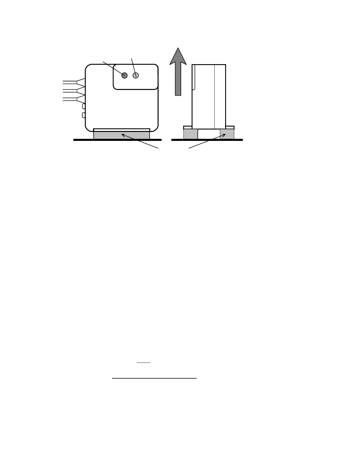
Figure 2.
Gyro orientation
The gyro sensor (together with the electronics of the gyro) is anti-vibration mounted inside the gyro case. However, to provide further vibration
and shock resistance it is important that the gyro be mounted to the airframe using two of the double sided adhesive foam strips provided. Do
not use any other type of mounting foam as this will reduce the performance of your gyro. Replacement strips are available as a CSM spare. For
good adhesion, ensure that the surface to which the gyro is attached is smooth, hard and clean. As with all high performance solid state gyro
systems, the ICG400 performs best if sited at a point of low vibration in the helicopter airframe. Where possible avoid siting the gyro at the
extreme front of the radio tray for example as this area is often subject to high levels of main rotor generated vibration. Also many plastic radio
trays are too flexible and better performance can often be gained by mounting the gyro at the rear of the frames.
Radio and tail linkage adjustment.
In our experience most problems with gyro systems arise from incorrect radio setup, incorrect servo arm length, or poor adjustment of the tail
control linkage. The following sequence is designed to avoid these snags and ensure a fault-free installation first time. You may need to consult
your radio control system manual in order to identify the receiver channels for the rudder and gain inputs to the gyro, however we have included
information for some commonly used systems later in this manual.
Radio Setup
First enter the menus of your transmitter and set up the rudder and gain channels as follows:-
•
Centre rudder trims and (if fitted) rudder sub trim.
•
Set rudder travel adjustment (ATV) to 90%. Most transmitters have separate adjustments for left and right movements and you should
make sure you have set the travel adjustment for both directions. At this stage (i.e. before the gyro has been installed) we are using this
value to help establish the right servo arm length. Once the gyro has been installed the rudder ATV is used to set the yaw rate demand.
•
Ensure that the rudder rates are set to the default value of 100%.
•
Set the gain channel travel adjustment to 60% (both ways)
•
Ensure that Automatic Tail Stabilisation (ATS) or 'REVO' mixing is INHIBITED.
•
Ensure that pilot authority mixing is INHIBITED
•
Put the throttle hold switch to the OFF position.
Rudder channel checks
•
At this point you should plug rudder servo directly into rudder output of receiver.
•
Turn on the radio and open and close the throttle. The rudder servo should not move as the throttle is operated. If it does, then ATS or
REVO mixing is still active.
You will need to inhibit it before proceeding
further.
Mid stick trim
•
With the rudder stick and trim centred make sure that servo arm is at right angles to tail push rod.
•
Now adjust push rod length until the pitch of the tail blades is about 8 degrees with the rudder stick centred. This will correspond
approximately to the pitch of the tail in the hover and ensures that the servo will be close to its mid position in the hover.
Servo arm length
•
Watch the tail rotor linkage while moving the rudder stick slowly fully left and fully right. If the linkage does not approach either extreme
of the pitch linkage travel then increase the servo arm length. Conversely, if the linkage binds at one extreme or the other then slightly
 Loading...