2, see the transmitter instruction manual pages 91 and 65.
This leaves the flight mode 1 switch available for gyro mode switching, the gyro channel will also be used. The ICG400 gyro is plugged into
the rudder channel and the auxiliary lead from the gyro is plugged into the gyro channel in the receiver, (Channel 5). The way in which it will
operate will be as follows: the gyro can be set for example to operate in conventional mode when in Normal Flight Mode with a gain of 70%,
and then in Heading Hold Mode with a gain of 70% when in Flight mode 1. Depending on whether or not you have a driven tail during autos
will determine what value you will need to use in Flight Mode 2 which will be Throttle Hold Mode.
You should experiment with settings until you are satisfied. The rotation or pirouette rate will still be controlled by the use of EPA on the rudder
channel (End Point Adjustment, see page 21 of the RD6000 instructions for details), and should be set to about 60% initially for both left and
right throws. This can be increased after flight testing if you require a quicker rotation rate. The ICG400 Auto set-up routine can still be utilised
by toggling the Flight Mode 1 switch a couple of times to enter this mode.
Flying the gyro
Turn-on sequence
1. Turn on your transmitter
2. With the model stationary on the ground turn on your receiver.
3. Wait for about
5 seconds keeping the model still
while the gyro goes through its self test/boot up sequence.
4. Move the rudder stick fully in both directions and ensure that the tail rotor servo responds to stick movements. (Do not move the gain
switch until the boot up is complete unless you wish to enter the auto setup routine.)
5. Your ICG400 is now ready for flight.
!! Make sure the model is not moved during the gyro self test period. !!
Initial flight trials.
We suggest that you
reduce the rudder travel adjustments in your transmitter to 60% for the first few flights until you get used to the
response of the gyro system
.
First select flight mode 1 (Heading Lock mode) and hover the helicopter. Use short small 'stabs' of rudder control to disturb the helicopter in
yaw and observe. If some tendency to oscillate is seen, slightly reduce the gyro gain. Conversely if no tendency to oscillate is seen try increasing
the gain. You are looking at this stage for the highest gain that gives no sign of oscillation when the tail is disturbed by sudden changes in tail
command. Observe any trim offset in the tail and correct this with the transmitter rudder trim.
Now switch to Flight mode 0 (Standard mode) and repeat the exercise above. If the mechanical trim adjustment of the tail linkage is within a
reasonable range of the correct setting the auto-trim built into this mode should compensate for the residual trim error and the trim state of mode
0 should match that of mode 1. If however you observe a trim difference between the modes this means that the mechanical trim of the tail is
outside the limits of the auto trim system.
Do not move the trim on the transmitter
but observe the direction of the trim error in mode 0 and
adjust the mechanical trim of the tail linkage to correct it. If the trim error in mode 0 causes the helicopter to rotate anticlockwise (a leftward
trim error) adjust the length of the pitch linkage to put more right tail pitch on and vice versa.
Once this has been done you may wish to check for tail wagging in fast forward flight. Should this be observed, you should lower the gyro gain
slightly. Caution should be exercised over the use of the Heading Lock mode in flying circuits or other general flying until you are familiar with
the very special handling characteristics that Heading Lock gives.
Adjusting the stick response
After initial setting use the rudder ATV, Rates, and Exponential facilities of the transmitter to tailor the control response as required.
Beware
that the ICG400 makes high rates of yaw available (at all gain settings).
If an increase in available yaw rate is required increase the rudder
travel on your transmitter
gradually
until the desired response is obtained. Remember that increasing the rudder travel adjustment will not
increase the overall tail servo throw as this is set by the gyro's own travel limiters.
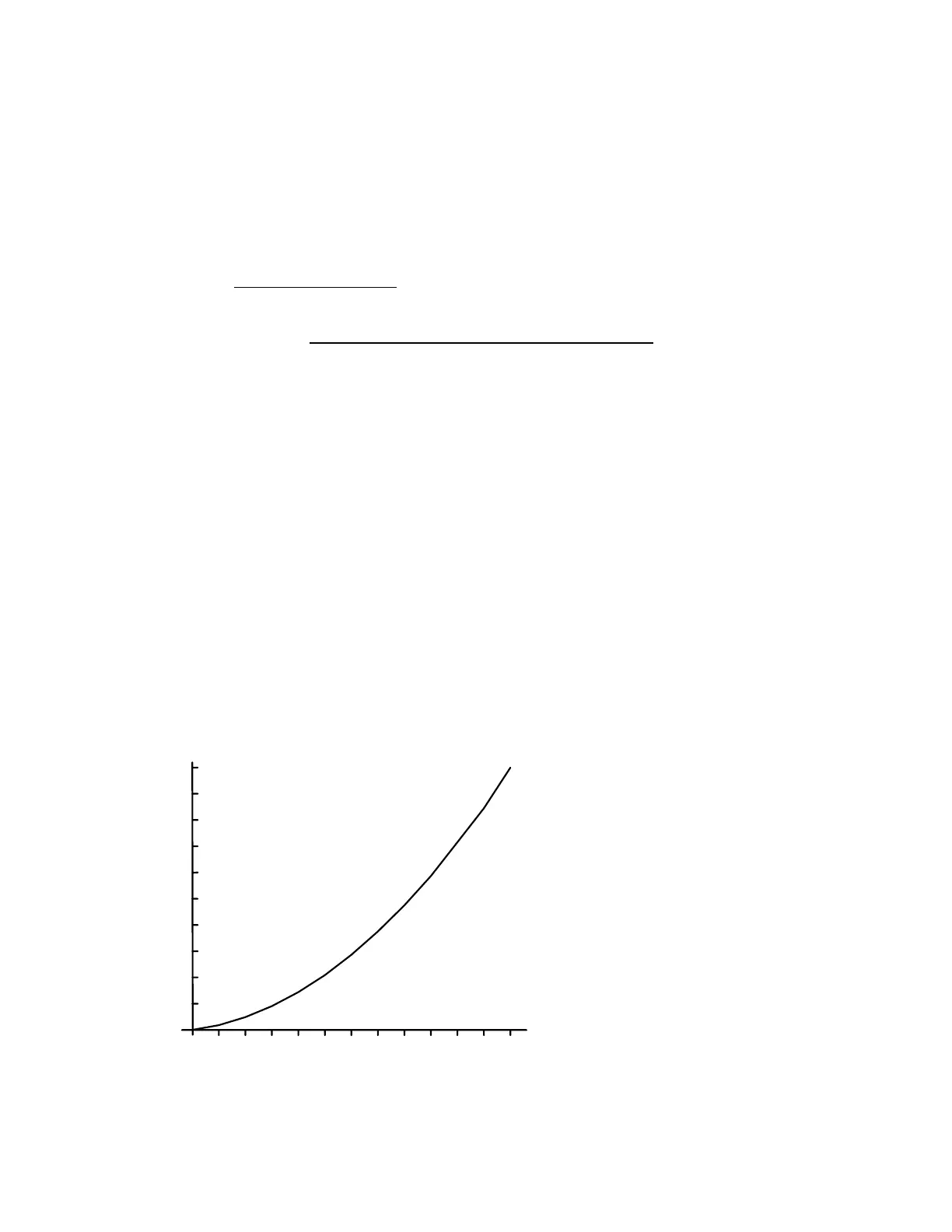
The ICG400 has built-in exponential. You may find the following graph of yaw rate against rudder command useful in deciding on the setting
of rudder rates and rudder ATV. Remember that the ATV and rates facilities work together so that setting the rudder ATV to 80% in both
directions and also setting a rudder rate of 60% will give a total rudder throw of 0.8 x 0.6 = 0.48 = 48%
10020 40 60 80
200
400
600
800
1000
Rudder channel throw ( % )
Yaw
rate
(deg./s)
1200
Figure 3. Yaw Rate Demand curve built in to the ICG400.
Automatic Tail Stabilisation (ATS)
This should not be used with the ICG400 gyro
 Loading...