reduce the servo arm length. Re-check the mid-stick pitch setup and repeat this test. You are looking to achieve a servo arm length that
gives full pitch linkage movement but avoids the linkage binding or the servo stalling. Many helicopters have pitch systems that do not
give equal throw about the hover pitch value. The ICG400 has independent servo throw adjustments for left and right which will
accommodate this and fine tuning of the servo throw is done later (in the auto-setup routine).
Rudder control sense
•
Now we must establish that the sense of the transmitter rudder control is correct (i.e. that the application of a right rudder command
causes a change in tail pitch that will rotate the model to the right).
Failure to do this will cause an uncontrollable pirouette on take-
off and beginners who are in any doubt on this aspect of the set-up should seek advice
To work out which way the tail rotor will go
just remember the leading edge (front) of the tail blades will point in the direction that the tail rotor will go, so for a left stick command
you want the tail blades to point to the right (tail swings to the right and the nose goes left). It is vital for this test that you have the tail
blades fitted the right way around!
Gain channel checks
•
Plug the rudder servo directly into the channel on the receiver you are going to use for the gyro gain/mode control. (This allows us to
check for correct gain channel operation).
•
Operate the gyro gain switch and observe the servo movement. If there is no movement check that you have correctly identified the gain
channel and its switch.
•
Now move the rudder stick over its full range and observe the rudder servo. If it moves then pilot authority mixing is still active. Disable it
and repeat this test.
Connecting the gyro
•
It is now time to connect the gyro into the system. Power down the radio and connect the servo to the gyro output and connect the gyro to
rudder and gain inputs to the correct receiver channels.
•
Power up, observing that the red gyro power LED comes on and wait 5 seconds while the gyro initialises.
•
Move the rudder stick and check that servo swings both ways. If it swings the same way for left and right stick movements you have the
rudder and gain inputs of the gyro transposed. Connect rudder and gain inputs correctly and repeat this test .
•
We must now identify which gain switch position gives mode 0 and which gives mode 1. The flight modes can be identified by the
different way the servo reacts in the two modes. For both gain switch positions hold the rudder stick at full travel for two seconds and
release to centre. If the servo returns close to mid position the gyro is in Standard mode (mode 0), while if the servo stays at or near full
travel the gyro is in Heading Lock mode (mode 1). For future reference note which switch position corresponds to which mode.
You should now have your gyro installed and have your radio and tail linkage set up correctly and may now proceed with the auto-setup routine
as described below.
The Auto-setup routine.
The unique auto-setup facility of the ICG400 allows the important parameters Rudder trim, Gyro sense, Servo type and Travel limits to be
quickly and simply set up from the transmitter. The setup is stored in the gyro's non-volatile memory so the routine will only need repeating if
one of these parameters needs to be changed.
Before entering the auto setup routine it is important that:-
•
All forms of mixing to the tail rotor channel (i.e. Automatic Tail Stabilisation, or throttle to tail rotor mixing) are inhibited.
•
The trim and sub trim of the tail rotor channel are centred.
•
The tail rotor servo operating sense has been correctly set in the transmitter.
Failure to do this will cause an uncontrollable pirouette
on take-off and beginners who are in any doubt on this aspect of the set-up should seek advice.
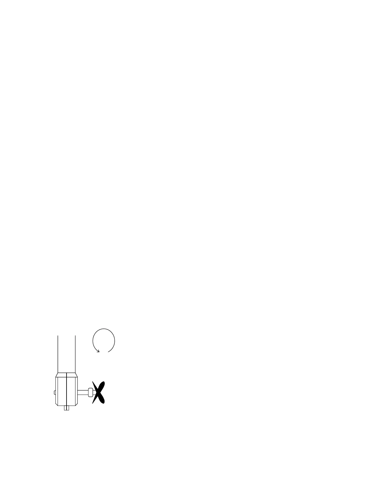
The correct operating sense can be
established by looking at the tail rotor blades. With a left tail rotor command held on, the leading edge of the tail blades are pointing to the
right (see Figure 3)
For LEFT tail command
the leading edge of the
tail blades point to the
RIGHT (as shown here)
Figure 3 Getting tail servo operating sense right.
If the tail blades move in the wrong direction the condition of the servo reversing of the tail rotor channel should be changed and the movement
of the tail blades re-checked.
Performing the auto setup
To access the auto setup you toggle the gain switch a couple of times during the gyro boot-up time (this is the first few seconds after the radio
system is powering up). The gyro acknowledges this by zipping the servo back and forth a couple of times before parking it in the mid position.
 Loading...