CANedge2 Docs, Release FW 01.04.02
Hardware revision ≥ 00.01
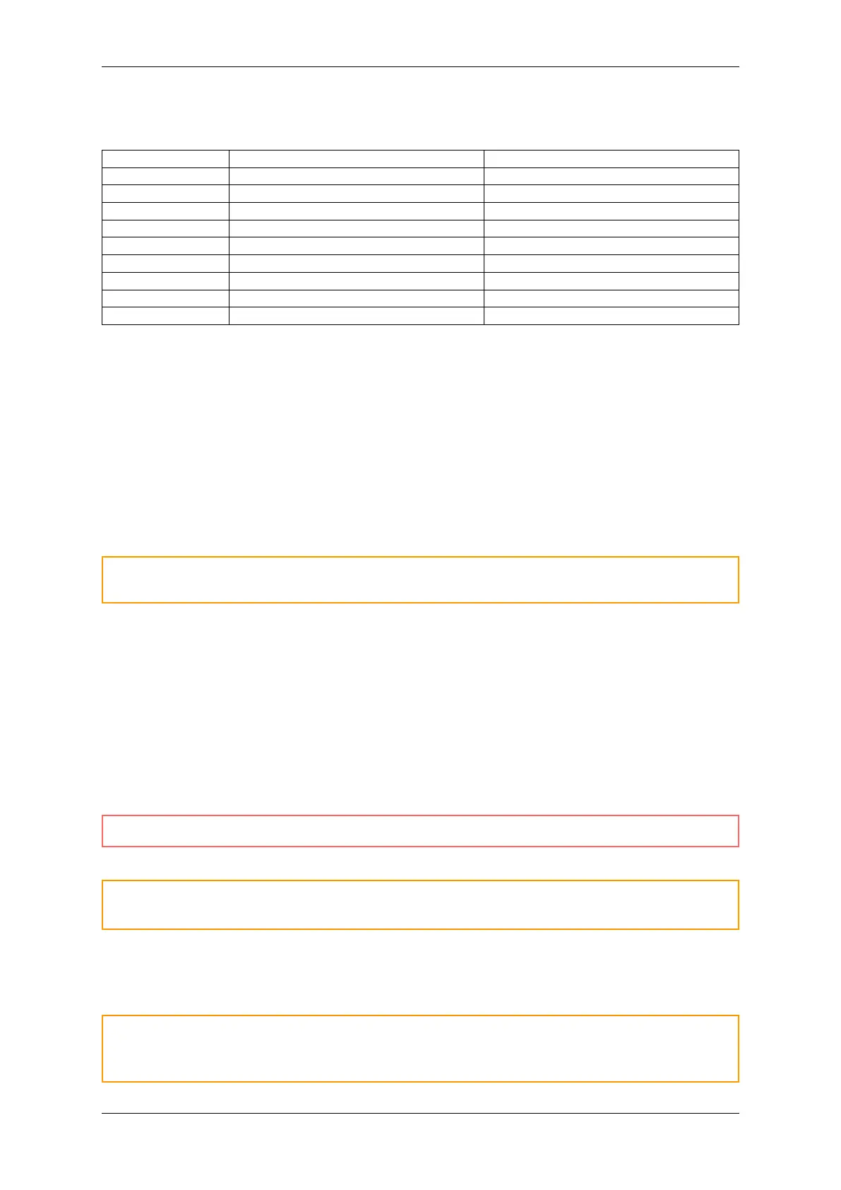
Pin # Channel 1 (CH1) Channel 2 (CH2)
1 NC 5V Supply Output
2 CAN 1 L CAN 2 L
3 GND GND
4 LIN Data 1 LIN Data 2
5 NC NC
6 GND (optional) GND (optional)
7 CAN 1 H CAN 2 H
8 NC NC
9 Supply & LIN1 VBAT LIN2 VBAT
Hardware revision = 00.00
The hardware 00.00 pinout can be found here.
Supply
The supply (CH1 pin 9) is used to power the device. The supply is internally protected against reverse
polarity and low-energy voltage spikes.
Refer to the Electrical Specification for more details on the device supply.
Warning: The supply line must be protected against high-energy voltage events exceeding device
limits
GND
All GND (ground) pins are connected internally.
5 V Supply Output
The +5 V output can be used to power external devices. The power can be toggled via the device
configuration. The output can deliver 1.5 A @ 5 V continuously.
Danger: Connecting external input power to this pin can permanently damage the device
Warning: External protection (such as clamp diodes) must be installed if inductive loads are
connected to the 5V Supply Output
CAN L/H
Warning: CAN-bus requires no common reference (ground). However, it is recommended that
GND (ground) is carried along with CAN-L/H to prevent that the common-mode voltage is exceeded
(resulting in transceiver damage)
0.3. Hardware 9