Laser Air Plus | User Manual Laser Air Plus | User Manual
1413
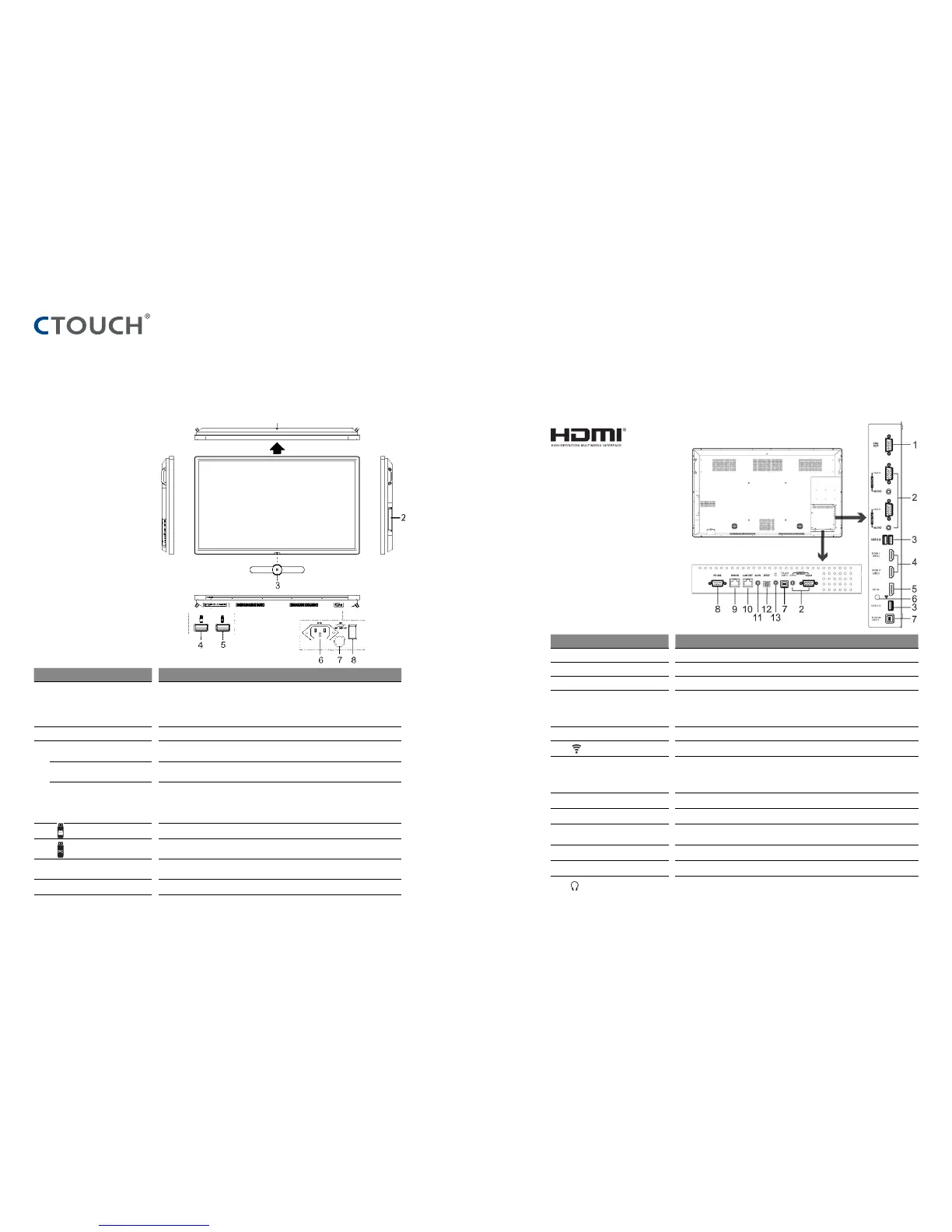
IDENTIFICATION OF CONTROLS IDENTIFICATION OF CONTROLS
nr. Description
1 USB(2.0)(for camera) This port is connected to PC (internal OPS), but is changed to Android if current source is
AV, USB or in home page.
Notes:
1. Please open the dust cover before being used.
2. It can perfectly support camera’s up to 720p.
2 Internal PC module slot Insert the CTOUCH Easy air PC module (Optional)
3 Power LED Red: In standby mode.
White: In power on mode.
Remote control sensor Aim the remote control towards this spot on the CTOUCH interactive display.
Power Press to turn on or off the CTOUCH interactive display.
Note: When the CTOUCH interactive display is turned on, press the button in middle to
show the navigation bar. Press the button for about 2 seconds and the screen will go into
stand-by mode.
4 USB port for the CTOUCH interactive display Andriod-surrounding.
5 USB port for Easy air PC module.
Note: If there is no Easy air PC module inserted, the USB port has no function.
6 AC IN Plug the AC cord into this jack and into a power outlet.
(AC 100-240V 50/60Hz)
7 Fuse 12A 250V
8 Power Switch Press ( I ) to connect the power, press (O) to cut off the power.
Note: Don’t cover the power switch.
nr. Description
1 VGA OUT Output of the currently selected PC IN 1/2/3 signal.
2 PC IN1/2/3 Connect the video/audio of a computer to these ports.
3 USB2.0/3.0 Connect USB devices to these ports.
4 HDMI1/2 INPUT Connect an HDMI or DVI device to this HDMI socket.
HDMI1(MHL): Connect a MHL- enabled device such as a smart phone to this jack to view
the external device’s screen on your screen.
HDMI2(ARC): Connect an ARC-enabled home theater receiver to this jack.
5 DP(DisplayPort) INPUT Connect an external device to DP socket.
6 Antenna WiFi antenna.
7 TOUCH OUT1/2 Output for external devices connected to PCx or HDMIx ports, which support touch
systems.
Note: TOUCH OUT 2 takes precedence over TOUCH OUT 1 in default. You can define it in
the Lock menu.
8 RS232 For remote control of the CTOUCH interactive display.
9 WAN IN The built-in router input port. Connects the external network.
10 LAN OUT The built-in router output port. Connects to another computer or other internet enabled
devices.
11 AV IN Input port for composite video.
12 S/PDIF digital audio output Connect a digital sound system to this S/PDIF socket..
13 Connect headphones to this jack. The current selected source is audible.
NOTE:
If the VGA or HDMI does not get any signal it will go into stand-by after two minutes. If there is no input on the AV it will go into stand-by mode after 10 minutes.
The terms HDMI and HDMI High-Definition
Multimedia Interface, and the HDMI Logo are
trademarks or registered trademarks of HDMI
Licensing LLC in the United States and other
countries.
CTOUCH Button