Series 1000 and 1500
28
• Remove the battery and battery tray from the
tractor.
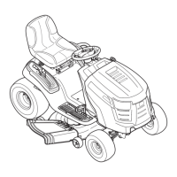
18.6. Inspect the upper drive belt: See Figure 18.6.
• Is the upper drive belt correctly positioned on the
tensioner pulley, transaxle input shaft pulley, and
the upper sheave of the variable speed pulley?
• Inspect the type and condition of the belt.
• Check the bearing on the tensioner pulley.
• Check the tensioner pulley arm: it should return
readily to static position under spring tension.
• The center partition of the variable speed pulley
should move up with light force and down under
it’s own weight.
18.7. The pulley on the transaxle input shaft should be
firmly attached.
• Early production tractors used a splined joint
between the pulley and the input shaft.
• Current production tractors carry the pulley on a
separate hub that fits over the splined shaft.
NOTE: The nut securing the pulley should be
tightened to a torque of 10-15 ft.-lbs using an 11/
16” wrench. Over-torquing the nut may shear the
input shaft. Replace the belleville washer
between the nut and the pulley if it is flattened.
NOTE: Some models used a special “fully fin-
ished” nut with an extended washer face. Do not
replace this nut with a standard nut unless a
washer is added between the nut and the pulley.
The washer must have a big enough O.D. to fit
over the star shape on the pulley adaptor, and
must be sufficiently thick to transfer compression
loads (from torquing the nut) directly to the pul
-
ley, not the adaptor.
18.8. Repair any problems found. If the upper drive
belt is correct and in serviceable condition, rein
-
stall it. If the upper drive belt needs to be
replaced, the lower drive belt should be replaced
as well. Refer to the “TRACTION DRIVE BELT
REPLACEMENT” section of this manual.
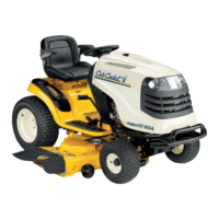
18.9. Operate the drive pedal while observing the
movement of the components controlled by the
drive pedal.
See Figure 18.9.
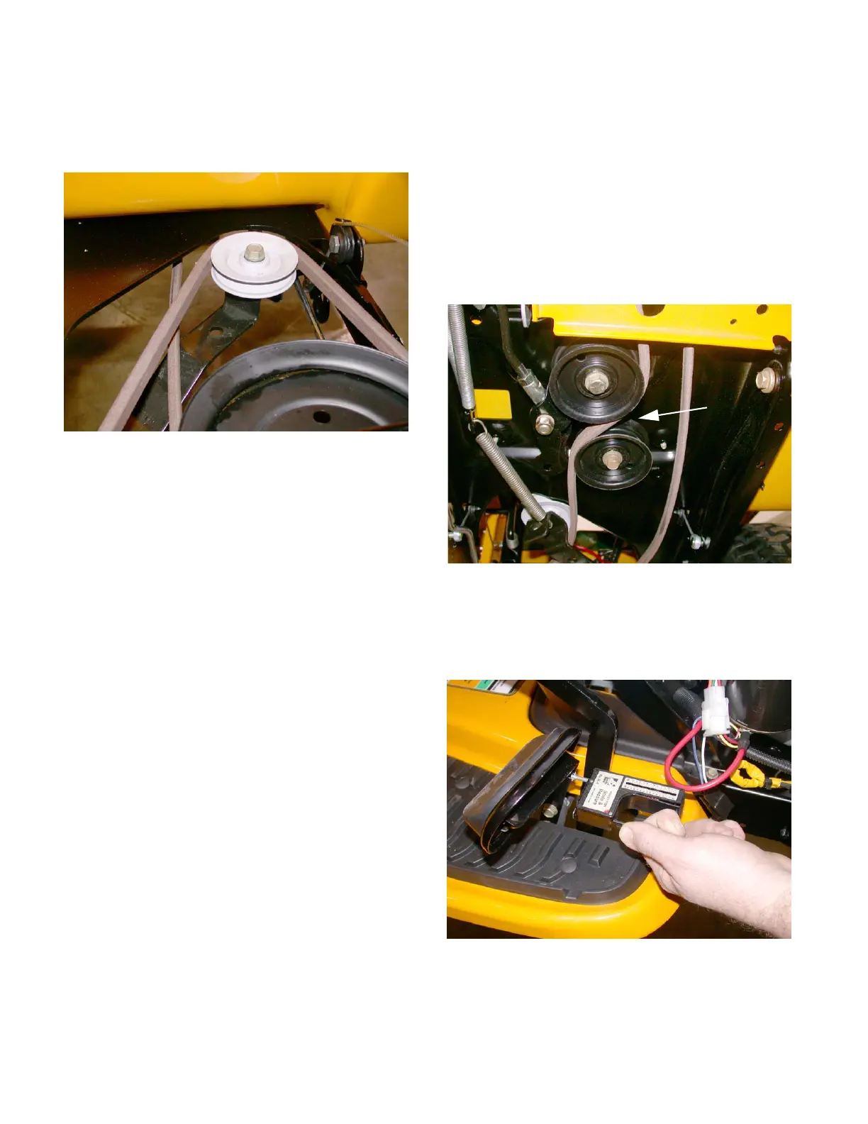
18.10.The double idler bracket should move with about
10 lbs pressure applied to the pedal, and return
under spring pressure as the pedal is released.
See Figure 18.10.
Figure 18.6
Figure 18.9
Observe
movement
Figure 18.10
 Loading...