Series 1000 and 1500
55
31.7. Turn-off the engine and allow it to cool before
starting to work on the tractor. To gain access to
the control linkage, perform the following three
steps:
31.8. Remove the cutting deck.
31.9. Lift and safely support the rear of the tractor.
31.10.Remove the rear wheels using a 3/4” wrench.
31.11.Move the control pedal through it’s range of
travel (with the parking brake released) and look
for the following conditions that will cause loss of
linkage motion:
• Pedal loose on the pedal shaft.
• Loose arm that connects the pedal shaft to the
control rod.
• Worn bushings supporting the pedal shaft.
• Worn ferrule or an elongated hole where ferrule
connects to pedal shaft.
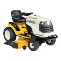
31.12.Disconnect the control rod from the pedal shaft
by removing the cotter pin that secures the
adjustable ferrule on the rod to the shaft.
See Figure 31.12.
31.13.Confirm that the pedal shaft moves freely in the
bushings, and does not bind.
31.14.Worn pedal shaft bushings are easily replaced
using the following 5 steps.
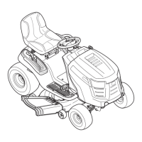
31.15.Set the parking brake and remove the drive
pedal using a T-40 driver.
See Figure 31.15.
Figure 31.12
Cotter pin
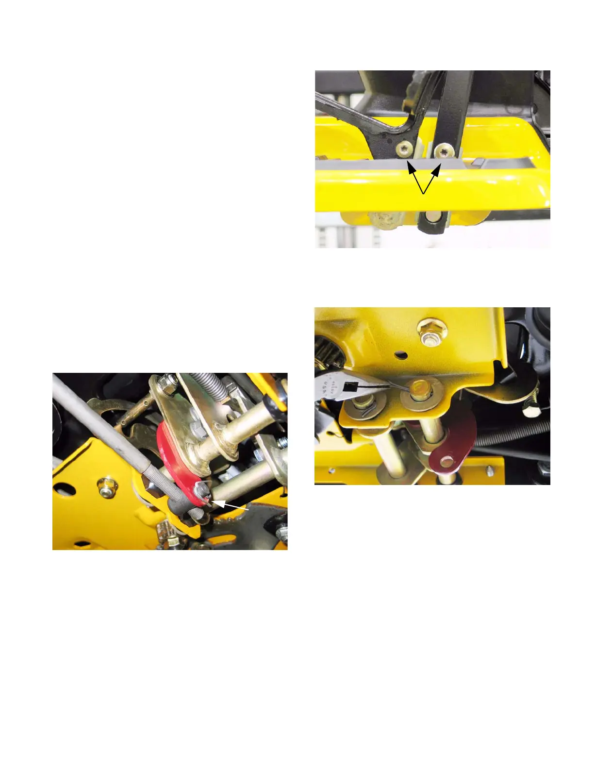
31.16.Remove and discard the cotter pin that holds the
inboard bushing in place.
See Figure 31.16.
Figure 31.15
T-40 screws
Figure 31.16
 Loading...