Series 1000 and 1500
57
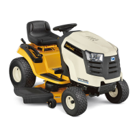
31.28.To adjust the hydro control rod: Find the Neu-
tral position for the control pedal, and set the
parking brake. The cam in the parking brake
mechanism will lock the pin on the pedal shaft
into Neutral.
See Figure 31.28.
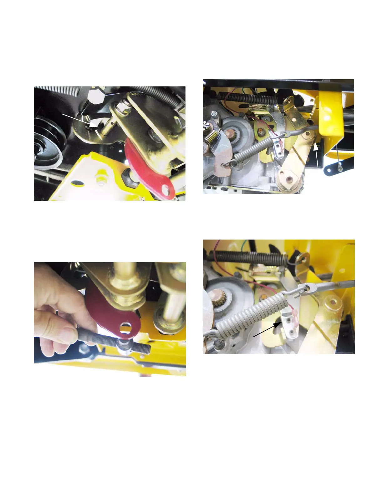
31.29.Thread the ferrule up or down the length of the
hydro control rod until the post is centered in the
hole that it fits into. At this point, the transaxle
and the linkage are both synchronized in Neu
-
tral. See Figure 31.29.
31.30.Secure the ferrule to the arm on the pedal shaft
using a new cotter pin.
Figure 31.28
Pin locked into neutral
Figure 31.29
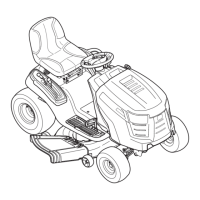
31.31.To adjust the input arm on the hydro: Confirm
that the roller on the return arm draws fully into
the valley in the cam surface on the front of the
input arm.
See Figure 31.31.
31.32.As the hydro control rod pulls forward on the
input arm, it first moves a ground contact against
the reverse safety switch.
See Figure 31.32.
31.33.After the switch contacts the ground, the hydro
control rod reaches the end of the lost-motion
slot, and begins to push the arm forward, to the
Reverse position. Excessive lost motion will
result in loss of ground speed in reverse.
Figure 31.31
Roller
Figure 31.32
Reverse switch

 Loading...