Series 1000 and 1500
66
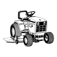
34.16.Disconnect the hydro relief rod from the relief
valve by removing the hairpin clip. Lift the rod off
of the arm that controls the valve, and remove
the rod from the tractor.
See Figure 34.16.
34.17.Detach the transaxle vent tube from the left
frame channel of the tractor.
34.18.Support the transaxle with a hydraulic jack.
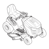
34.19.Remove the two screws that connect the tran-
saxle to the stabilizer bracket using a 9/16”
wrench.
See Figure 34.19.
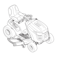
34.20.Remove the pair of nuts and bolts that fasten
each axle housing of the transaxle to the brack
-
ets on the tractor frame. Use a pair of 1/2”
wrenches.
See Figure 34.20.
34.21.Carefully lower the transaxle to the ground.
34.22.Installation notes are as follows:
34.23.Fill the transaxle with fluid before installing it in
the tractor. Some dealers have devised ways to
manually drive the input shaft and purge the air
from the drive system on the bench, prior to
installation.
34.24.If bench purging is not available, follow the purg-
ing instructions described in the “TRANSAXLE
SERVICE AND MAINTENANCE: HYDRO
-
STATIC GT” section of this manual after the tran-
saxle is installed.
34.25.Reverse the removal process to install the tran-
saxle.
• Tighten the screws to the torque bracket to a
torque of: 35 ft.-lbs.
• Tighten the bolts holding the axle housings to
the brackets to a torque of: 250 in-lbs.
• Tighten the screws holding the fan to the pulley
to a torque of: 30-35 in-lbs.
• Tighten the lug nuts to a torque of:
34.26.Test run the tractor in a safe area that is free of
hazards, obstacles, and bystanders to confirm
correct operation and adjustment before install
-
ing the cutting deck. Make any necessary adjust-
ments.
Figure 34.16
Relief valve
Figure 34.19
Remove
these 2
screws
Figure 34.20
Remove
these 2
nuts and
bolts

 Loading...