12
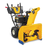
5. While manipulating the lift handle to keep the
channel brackets parallel to the tractor frame, lift
upward on the front lift shaft and slide the snow
thrower assembly rearward until the channel
brackets are fully inserted into the frame channels.
Secure the assembly to both sides of the frame
using the hex cap screws (9, Fig.2) and bell
washers (15, Fig.2). See Figure 18.
Figure 18
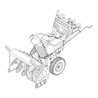
6. Tractors with 15” front tires ONLY. Align the
gearbox mounting bracket with the subframe arms
and reinstall the front hex cap screws and flange
lock nuts. Tighten the rear fasteners. See Figure 19.
Figure 19
IMPORTANT: Series 2500 Tractors Mfg. Date K015
and After. To open the tractor hood, the snow thrower
must be lowered to the ground and the discharge chute
rotated to the straight forward position.
7. Raise the tractor hood. Refer to the tractor
Operator’s Manual.
NOTE: Use the 754-0441 (D) PTO belt for single
cylinder engines ONLY. Use the 754-3075 (E) belt for
twin cylinder engines ONLY.
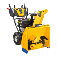
8. Install the appropriate PTO belt (D or E) on the
PTO clutch pulley on the front of the engine by
passing the belt upward inside the front of the
tractor frame. Make certain the narrow side of the
PTO belt engages the groove of the clutch pulley.
See Figure 20.
Figure 20
9. Twist the PTO belt 1/4 turn inward to engage the
narrow sides of the belt in the grooves of the
tractor’s two front idler pulleys. Refer to Figure 20.
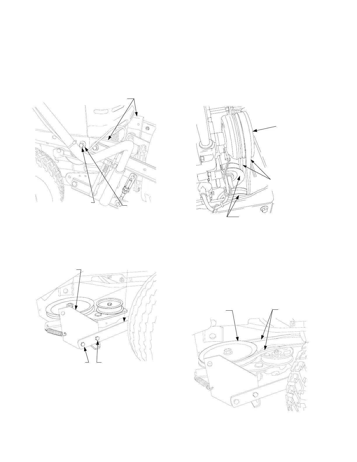
10. Routing the PTO belt rearward under the tractor
frame, install the narrow side of the belt in the V-
pulley on the snow thrower gearbox. See Figure
21. Make certain there is no more than a 1/4
inward twist in both runs of the belt.
Figure 21
BELL WASHER
HEX CAP
SCREW
CHANNEL BRACKETS
FULLY INSERTED
SUBFRAME ARM
GEARBOX
MOUNTING
BRACKEY
REINSTALL
FRONT FASTENERS
TIGHTEN REAR
FASTENERS
FRONT IDLER PULLEYS
PTO CLUTCH
PTO BELT
PTO BELT
V-PULLEY
 Loading...