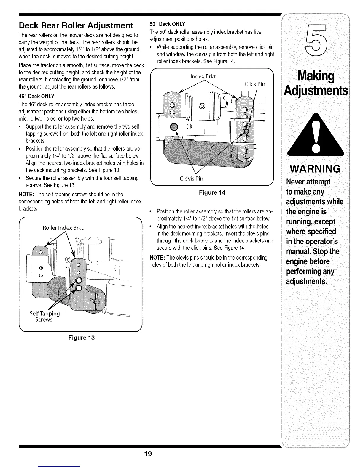
Deck Rear Roller Adjustment
Therearrollersonthemowerdeckarenotdesignedto
carrytheweightofthedeck,Therearrollersshouldbe
adjustedtoapproximately1/4"to 1/2"abovetheground
whenthedeckis movedtothedesiredcuttingheight,
Placethe tractorona smooth,flatsurface,movethe deck
tothedesiredcuttingheight,andchecktheheightofthe
rearrollers,Ifcontactingtheground,orabove1/2"from
theground,adjustthe rearrollersasfollows:
46" DeckONLY
The46"deck rollerassemblyindexbrackethasthree
adjustmentpositionsusingeitherthebottomtwoholes,
middletwoholes,ortoptwoholes.
• Supporttherollerassemblyandremovethe two self
tappingscrewsfromboththeleftand rightrollerindex
brackets,
• Positionthe rollerassemblyso thatthe rollersare ap-
proximately1/4"to 1/2"abovetheflatsurfacebelow,
Alignthenearesttwoindexbracketholeswithholesin
thedeckmountingbrackets,SeeFigure13,
• Securetherollerassemblywiththefour selftapping
screws.SeeFigure13.
NOTE:Theselftappingscrewsshouldbein the
correspondingholesof boththeleftand rightrollerindex
brackets,
Roller Index Brkt.
0
Self Tapping
Screws
Figure 13
50" DeckONLY
The50" deckrollerassemblyindexbrackethasfive
adjustmentpositionsholes,
• Whilesupportingtherollerassembly,removeclickpin
andwithdrawthe clevispinfromboththeleftand right
rollerindexbrackets,See Figure14,
Index Brkt.
Click Pin
Clevis Pin
Figure 14
• Positionthe rollerassemblysothatthe rollersareap-
proximately1/4"to 1/2"abovethe flatsurfacebelow.
• Alignthe nearestindexbracketholeswiththe holes
inthedeckmountingbrackets.Inserttheclevispins
throughthe deckbracketsandthe indexbracketsand
securewiththeclick pins.See Figure14.
NOTE:Theclevispinsshouldbe inthe corresponding
holesofboththeleft andright rollerindexbrackets.
ustments
WARNING
Neverattempt
to makeany
adjustmentswhile
theengineis
running,except
wherespecified
intheoperator's
manual.Stopthe
enginebefore
performingany
adjustments.
19

 Loading...