Continue holding the blade onto the star hub of the
spindle, and remove the flange nut and cutting blade.
Repeat the previous steps to remove the other blade.4.
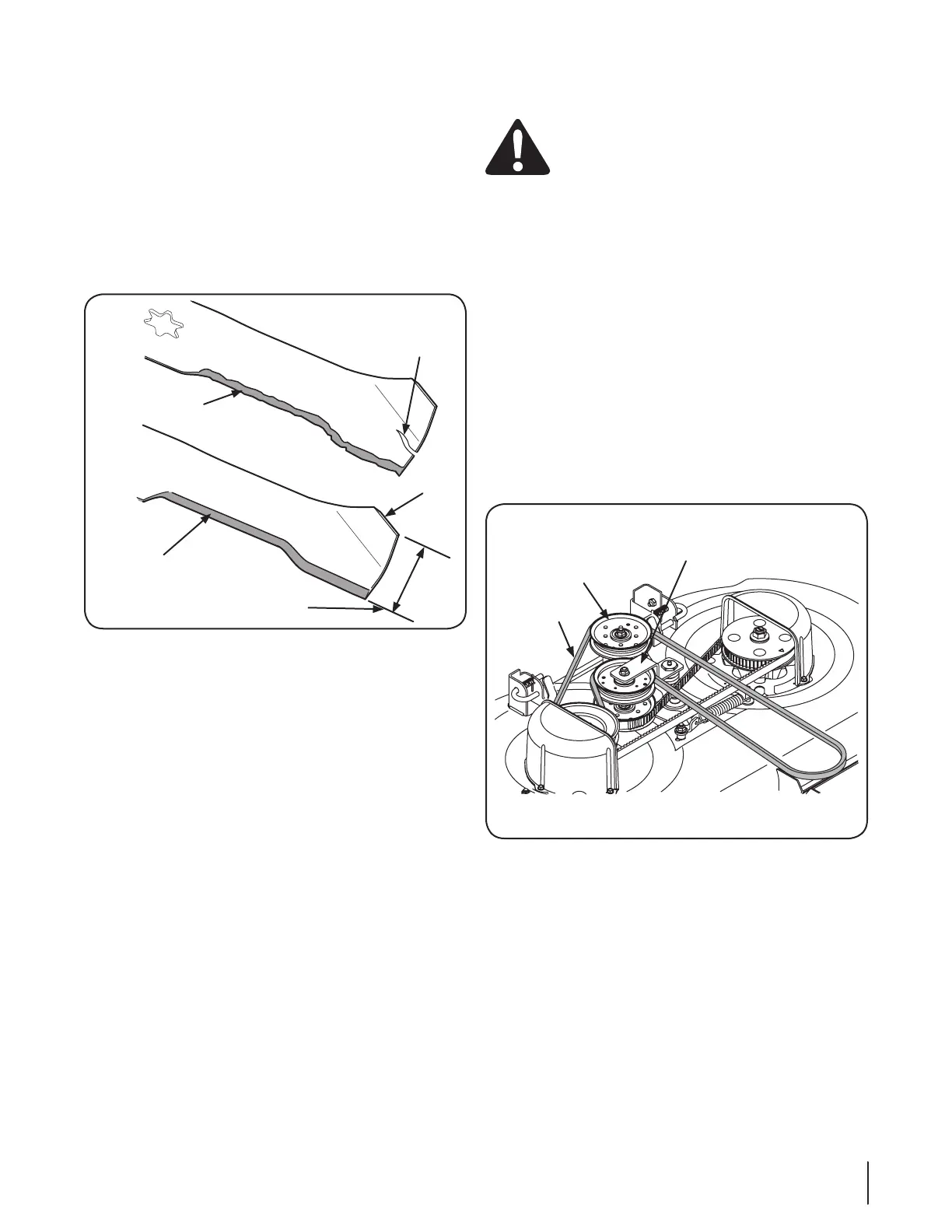
To properly sharpen the cutting blades, remove equal 5.
amounts of metal from both ends of the blades along the
angle.
NOTE: If the cutting edge of the blade has already been
⁄
separation is present, replace the blades with new ones.
It is important that each cutting blade edge be ground 6.
equally to maintain proper blade balance.
A poorly balanced blade will cause excessive vibration and 7.
may cause damage to the tractor and result in personal
injury. The blade can be tested by balancing it on a round
shaft screwdriver. Grind metal from the heavy side until it
balances evenly.
NOTE: When replacing the blades, make certain the side
mower is turned to the operating position.
NOTE: Note that the stars of the blades (and spindles)
are not symmetrical. The blade can be installed on each
spindle in only one direction. Carefully align the star hole of
the blade with the star of the spindle shaft when installing
shaft, and attempt to seat the blade onto the spindle by
tightening the hex flange nut.
Rotate the blade as necessary to align its star hole with 8.
the star of the spindle shaft, then slide the blade onto the
spindle shaft. Thread the hex flange onto the spindle shaft
and use a torque wrench to tighten the hex flange nut to
70 to 90 foot-pounds.
Repeat the above procedure to install the other blade.9.
Separation
1-⁄
Changing the PTO Belt
Be sure to shut the engine off, remove
ignition key, disconnect the spark plug wire(s) to
prevent unintended starting before removing the
belt(s).
All belts on your tractor are subject to wear and should be
replaced if any signs of wear are present.
NOTE: Do not use substitute belts. The V-belt found on your
tractor is specially designed for optimal performance and service
belts.
Remove the deck from beneath the tractor (refer to Cutting
Deck Removal).
2.
on the spring loaded idler bracket.
NOTE: It may be necessary to loosen the hex cap screw and
flange lock nut securing the pulley to the idler bracket to fit
the belt between the pulley and bracket.
Slide the belt between the bottom of the idler pulley and
top of the timing belt idler pulley below. See Fig. 7-4.
Loop the belt and push out of the V- groove of the drive 4.
pulley on the right hand spindle assembly. Lift the belt over
the pulley and out from beneath the spindle cover. See Fig.
7-4.
5.
drive pulley and spindle cover. Maneuver the belt around
and into the V-groove of the drive pulley.
Route the back side of the belt around idler pulley and 6.
between the idler pulley and idler bracket. Re-tighten the
hex screw and flange lock nut if loosened earlier. Refer to
Fig. 7-4.
Route the belt around the fixed idler pulley as shown in Fig. 7.
7-4 and re-install the deck as described in “Reinstalling the
se c t i O n 7 — se r v i c e

 Loading...