13Section 2 — ASSembly & Set-Up
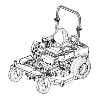
8. Move the upper ROPS section to the upright position, and
insert the locking pins with their retainer hairpin clips. See
Figure 2-6.
Locking Pin
Locking Pin
Retainer
Hairpin
Clips
Figure 2-6
Adjusting Drive Control Levers
The RH and LH drive control levers can be adjusted up or down
and fore-and-aft for the comfort of the operator. Proper drive
control lever and seat adjustment will result in the following:
In the neutral position with hands on the control levers,
• Operator’s upper arms should be relaxed and
approximately vertical.
• Operator’s forearms should be approximately horizontal.
In the full forward position,
• Operator’s back should stay in contact with the seat back.
• Control levers should not contact operator’s legs.
In the full reverse position,
• Control levers should not contact the operator’s legs or torso.
Set the seat to the preferred operating position.
• Adjustment lever is located under the front edge of the
seat.
Check factory settings of control levers for the conditions listed
above.
NOTE: If control lever adjustments are required, height
adjustments should be made prior to angular adjustments.
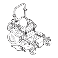
To adjust the height of the drive control levers:
1. Remove the flange lock nuts that secure the carriage bolts
in the drive control levers. See Figure 2-7.
Flange
Lock Nuts
Carriage
Bolts
Figure 2-7
2. Remove the carriage bolts from the drive control levers and
reposition to the second set of holes in the mounting block.
3. Reinstall the carriage bolts and flange lock nuts, and tighten
to 28-34 ft-lbs.
4. The same adjustments should be made to both sides of the
mower.
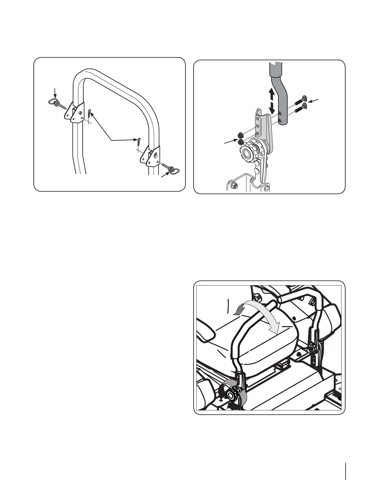
To adjust the front-to-rear angle of the drive control levers:
1. Loosen the control lever knob to unlock the drive control
levers. See Figure 2-8.
Figure 2-8
2. Move drive control levers to the desired angle and retighten
the drive control knob to secure the lapbars in place.
3. Check the results of any adjustments to the conditions
described above. Repeat any adjustment procedures as
required until all conditions are met.
 Loading...