Smart Controller Circuit Board Layout 25
Cat. No. 01024821
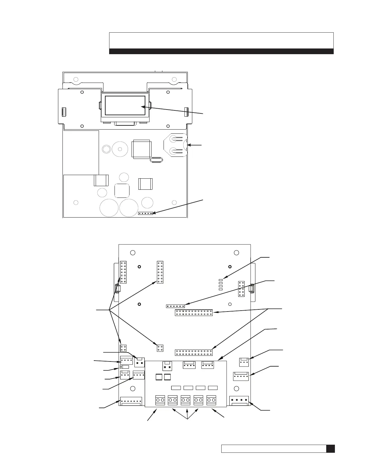
Smart Controller Circuit Board Layout
Smart Controller Circuit Board Layout–Front
Figure 31. Smart Controller circuit board layout, front view.
Smart Controller Circuit Board Layout–Back
POSITION
DC
MOTOR
FLOW
METER
RS485
BRINE
TANK
J22
2.5v
24v
AQUA SENSOR
AUX OUT4
AUX OUT3
AUX OUT2
AUX OUT1AUX INPUT
Figure 32. Smart Controller circuit board layout, rear view.
Keypad connector
Battery
CR2032 (Postitive Side Up)
Pull protective tab before activating
power to activate the battery
OLED Display
Optional AUX 5 Relay
Board Connection
Data Port PLC Output
RF Board Connection
(for remote)
Optional Auxilary Board
Optional AUX 6
Optional Aqua-Sensor
Cable
Power Cable
(from transformer)
Optional Blocking Valve Connection
Optional Programmable
Outputs
Optional External regeneration signal
connection or external alarm
Optional Smart Brine
Tank Cable
Flow Meter Cable
Optional Communication
Cable
Multiple Unit Jumper
Position Sensor
Cable
Motor Connection
Optional Modem
Connections

 Loading...