B
Brenda RoblesAug 16, 2025
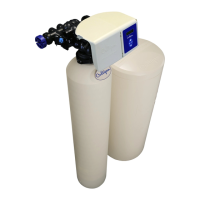
How do I fix a loss of water pressure in my Culligan High Efficiency 1.5 Twin?
- FfsparksAug 17, 2025
A loss of water pressure in your Culligan Water Dispenser might be due to a control and/or resin bed plugged with debris or iron build-up. Clean the control and increase the frequency or duration of regenerations or backwashes. If the inlet manifold is plugged, remove the control from the tank and clean it. Also, check the eductor screen/nozzle for any blockages.