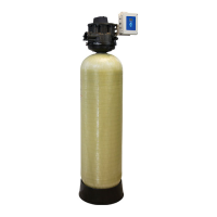
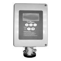
Do you have a question about the Culligan CTM Series and is the answer not in the manual?
Emphasizes reading the manual before operating the softener for familiarization.
Outlines the manual's content and purpose for operators.
Details safety guidelines and hazard warnings for installation and operation.
Defines hard water and acceptable levels based on calcium and magnesium concentration.
Explains the negative impacts of hard water on equipment and efficiency.
Details the ion exchange process using resin to remove hardness minerals.
Explains resin saturation, the regeneration process, frequency, and control methods.
Details the four steps of the resin regeneration process: backwash, brine draw, slow rinse, fast rinse.
Lists operational parameters and flow specifications for CTM water softeners.
Lists necessary components and details the sizing kit for installing a CTM Softener.
Provides guidance on selecting a suitable location for the softener unit.
Details the process of installing the distribution system components.
Explains the procedure for loading resin and underbedding into the media tank.
Instructions for attaching tank adapters to both Aqua-Sensor ported and non-ported tanks.
Describes how to properly mount the control valve onto the tank adapter.
Details the installation and connection of the plumbing adapter.
Guidelines for installing piping and using the bypass valve for operational purposes.
Illustrates recommended piping configurations for single-tank systems.
Provides instructions and safety warnings for connecting the drain line.
Details the installation of the drain line flow control and adapter.
Instructions for installing the pressure relief valve.
Guides on replacing the eductor nozzle and throat components.
Instructions for replacing the brine refill flow control insert.
Steps for installing the brine tank and associated piping.
Details on tubing the pilot valve for water and air operation.
Illustrates the front layout of the smart controller circuit board.
Details the rear layout of the smart controller circuit board and its connections.
Details connections for the motor and position sensor on the circuit board.
Steps for preparing the controller enclosure for wiring.
Guidelines for routing cables to the circuit board, maintaining separation.
Instructions for wiring the smart controller power cord and 24V transformer.
Explains tubing ball valves for multi-tank systems to alternate between service and standby.
Wiring diagrams for motorized ball valves in multi-tank configurations.
Instructions for setting jumpers for GBE to GBE RS485 communication.
Explains progressive, parallel, and alternating flow connection diagrams.
Guidelines for connecting multiple GBE boards to 24VAC power supplies.
Details the installation of the ported plumbing adapter.
Instructions for installing the gauge and sample valve kit.
Instructions for mounting and tubing the softening cartridge.
Guidelines for installing and positioning the Aqua-Sensor probe.
Explains the function and programming of auxiliary outputs for 24VAC devices.
Instructions for installing and wiring the auxiliary output 5 relay board.
Steps for installing the modem into the controller or remote.
Guidelines for selecting a location and mounting the wireless remote monitor.
Information on installing and programming the Smart Brine Tank Probe.
Steps to convert the multi-tank system to a non-hardwater bypass.
Instructions for filling and pressurizing the media tank.
Guidance on filling the brine tank with salt and understanding terms.
Procedure for sanitizing the water softener system.
A checklist to ensure the system is properly installed before use.
Precautions for maintaining the appearance and operation of the unit.
Provides a schedule for inspecting system components and reasons for maintenance.
Outlines a three-step process for analyzing system problems.
Lists necessary tools and procedures for checking the system's operation.
Provides a step-by-step procedure to safely depressurize the system for servicing.
Detailed steps for removing and disassembling the control valve for piston rebuild.
Instructions for disassembling the upper manifold of the control valve.
Steps to remove the pistons from the valve body.
Details the components of large and small flow valve assemblies.
Instructions for replacing T-seals and assembling flow valve components.
Steps for reassembling the control valve manifold.
Steps for reassembling the control valve onto the tank adapter.
Steps for disassembling the pilot valve for rebuild.
Instructions for replacing the motor assembly.
Procedure for replacing the pilot valve spool.
Steps for reassembling the pilot valve after service.
Troubleshooting steps for issues with the drain line flow control.
Diagnosing problems related to water levels and rod movement in the brine tank.
Table providing brine draw and slow rinse times for various models.
Common leak issues: drain, pilot valve, valve core, and hard water leakage into service lines.
Troubleshooting for restricted service flow, brine draw, refill failures, and media to drain.
Addresses pilot valve pressurization, brine tank overfilling, and standby mode problems.
Details the operation of motorized ball valves and their positions in different cycles.
Details piston locations and cycle positions for various valve operations.
Illustrates piston locations and their cycle positions within the flow valve.
Shows piston positions during the backwash cycle.
Details piston positions during the brine draw and slow rinse cycles.
Shows piston positions during the fast rinse cycle.
Details piston positions during the fill cycle.
Guides on recording diagnostic data for Aqua-Sensor analysis.
Explains how to interpret Z-ratio, Z-minimum, and Z-increase readings.
Lists models, sizes, part numbers for tanks and media.
Details the components included in various sizing kits for installation.
Exploded view and list of parts for the control valve assembly.
Lists various control valve parts, adapters, and accessories.
Details O-ring and piston rebuild kits for valve maintenance.
Lists piston replacement kits, valve core replacement, and pilot valve rebuild kits.
Lists components for the Culligan GBE controller.
Combines parts lists for different brine system sizes.
Details parts for the 3/4" brine valve subassembly.
Lists parts for the Aqua-Sensor probe and plug.
Lists parts for the remote display and related accessories.
Lists international versions of remote display parts and accessories.
Guides on ordering retrofit kits and plumbing adapters for conversion.
Provides guidelines for applying the Aqua-Sensor based on water parameters.
Table correlating water hardness to recommended salt dosage.
Details resin capacity per inch at different salt dosages.
Instructions and format for logging system operation data for troubleshooting.
Outlines the warranty period and conditions for the water conditioner.
| Power Source | Electric |
|---|---|
| Voltage | 120V |
| Type | Countertop |
| Dispensing Options | Cold |
| Filter Life | 6 months |
