Service and Repair 51
Cat. No. 01029401
CTM Piston Rebuild (Refer to page 84 for Kit Options)
Valve Removal and Disassembly
1. Having bypassed and depressurized (page 50) the system, disconnect from the valve; the pressure relief
valve (PRV), vacuum breaker, drain adapter and plumbing adapter.
2. Separate the plumbing at the unions, if necessary to remove the plumbing adapter from the valve.
3. Disconnect the tubing from the pilot valve at the inlet and drain ports on the valve.
4. Disconnect the wiring and remove the GBE controller by removing the two mounting screws, if using a front or
side mount bracket.
5. Remove the tank adapter clamp by loosening the bolts on both sides and lift the valve body from the tank. (see
Figure 70 on page 58)
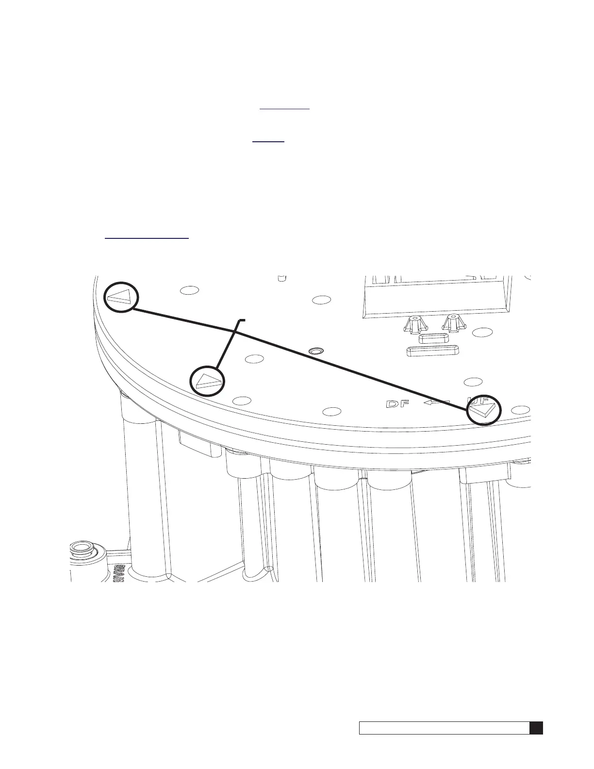
6. Remove 16 #3 screws from the top manifold, including the two under the enclosure, then remove the top mani-
fold by prying at the pry points. (see Figure 57)
Figure 57.
Top Manifold Pry Points

 Loading...


