Installation 15
Cat. No. 01029401
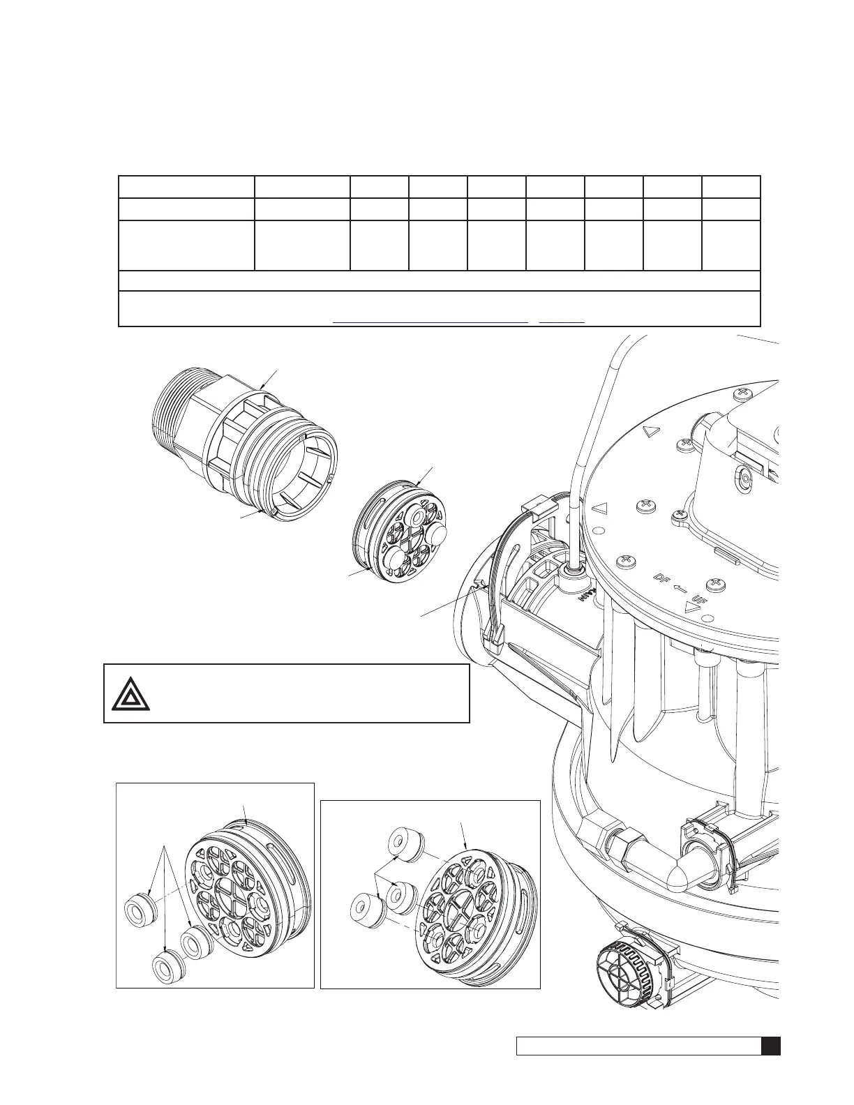
Drain Line Flow Control (DLFC) and 1.5” Drain Adapter
Table 4. Drain Line Flow Control
Model
60K 90K 120K 150K 210K 300K 450K 600K
Body/Flow Rate
3.5 gpm 5 gpm* 6 gpm* 8 gpm* 10 gpm* 12 gpm* 20 gpm* 30 gpm*
Inserts
0.4 gpm Black,
0.4 gpm Black,
2.5 gpm Black
Plug,
Plug,
Blue
Plug,
Plug,
Red
Plug,
Plug,
Green
Plug,
Blue,
Blue
Plug,
Red,
Red
Blue,
Blue,
Orange
Orange,
Orange,
Orange
*This is the same body. The inserts are changing the flow rate.
There four different installation kits for the CTM softeners; please make sure to use the correct installation kit for
the softener size being installed. See “Sizing Kits, Downflow” on page 78 - page 80 for more details.
Figure 12.
Push in hard on drain adapter until this
corner is flush with the valve.
Lubricate o-ring
Lubricate
o-ring
Insert drain line flow control in
this orientation.
Push down on clip, while
holding the adapter in place.
CAUTION! Clip was designed to stay attached
to the valve. Do NOT try to detach.
Flow Control Body
Flow
Control
Inserts
90K and Larger
Drain Assembly
Flow
Control
Inserts
60K Drain Assembly
Flow Control Body

 Loading...


