38 Culligan® Culligan Top Mount (CTM) Water Softeners
38 Cat. No. 01029401
Modem
Refer to GBE Programming for Commercial Softeners and Filters (except for HFxN) Manual (P/N 01027295) for program-
ming information. This manual can be obtained from your local dealer, CPort (www.cport.culligan.com) under the Techni-
cal Service Tab or on the Service Tech App.
Installing the Modem (P/N 01020747)
NOTE The modem can be installed into either the back of the main controller or the back of the remote con-
trol board. The functionality of the modem is the same in either installation.
NOTE Use of the modem kit requires a one-year subscription to either a Level 1 or Level 2 Telecom package.
Self-service registration is available at www.cport.culligan.com under the Technical Service tab on the
Telemetry page’s subpage called Setup Self-Service.
1. Before installing the modem into the back of the Smart Controller board or the back of the remote, the Smart
Controller circuit board or the remote must first be powered off.
2. When handling all circuit boards, take care to only touch the edges of the circuit boards—not the metal pins.
The electronics on all circuit boards can be damaged by static electricity.
3. Make sure all of the pins at all four connectors are aligned between the modem board and the main controller
board. Make sure that the modem board is fully seated into all four sockets.
4. When all connections have been made restore power.
5. Connect the modem to the telephone line by plugging a standard RJ-11 phone extension cord into the modem
board.
NOTE The Landline Modem is designed to plug into an analog telephone line (standard residential phone
line). This includes phone lines connected to most residential VoIP (voice over Internet) phone sys-
tems and to residential DSL phone systems. If you are connecting the modem to a DSL phone system,
follow the DSL provider recommended method to connect standard phones to the DSL service. Many
systems recommend or require the use of DSL line filters between the phone jack and the device.
NOTE Try to place the Smart Controller or Remote Display with the Landline Modem near a telephone jack. A
splitter might be needed if the jack is already in use.
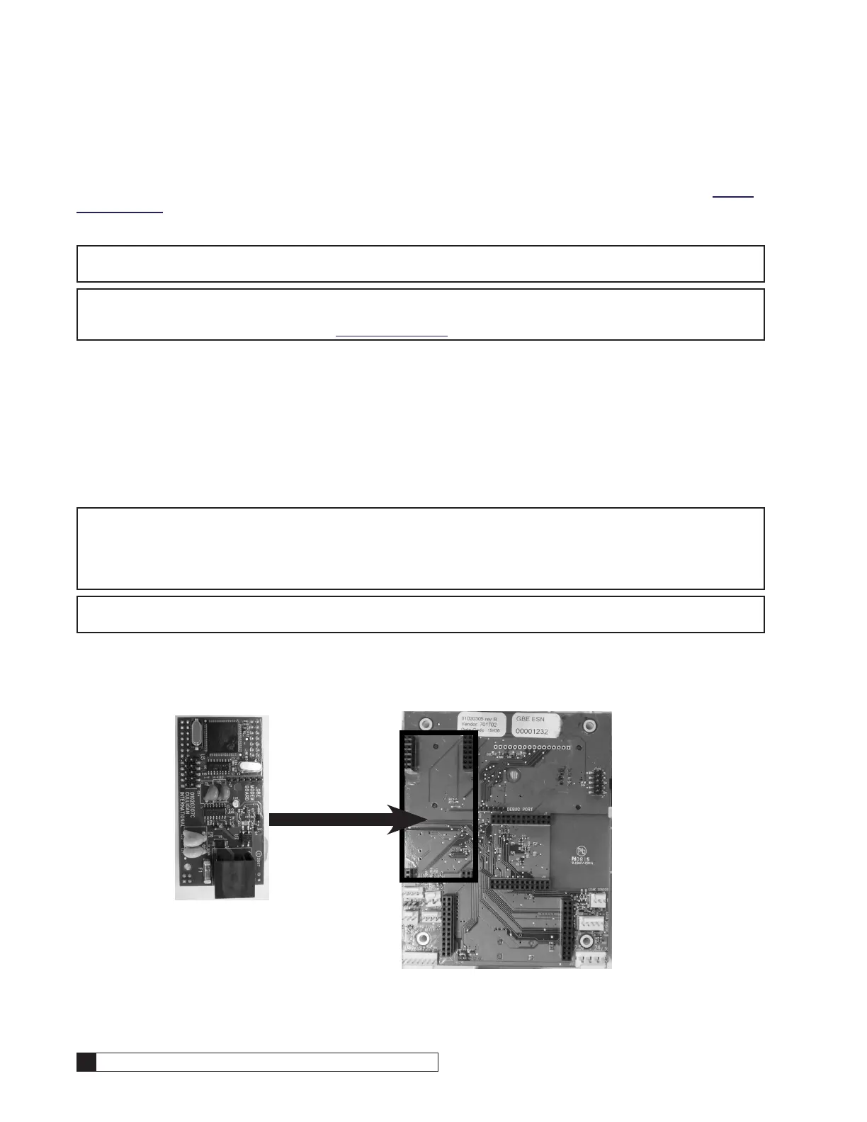
Installing the Landline Modem on the Smart Controller Board
Open the controller cover and locate the modem connection on the back of the board (see Figure 49). Insert line modem
board (P/N 01020747) into the socket on the back of the board. Make sure that all of the pins in all four connectors are
aligned and make sure the modem is fully seated into all of the sockets.
Figure 49. Back of GBE board.

 Loading...


