Smart Controller Circuit Board Layout 25
Cat. No. 01029401
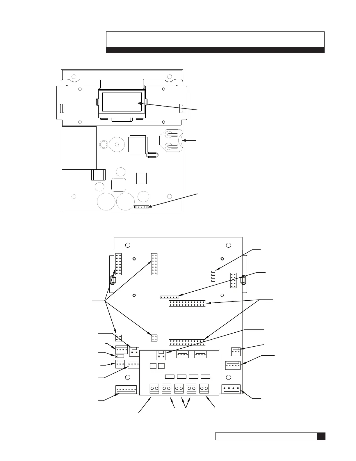
Smart Controller Circuit Board Layout
Smart Controller Circuit Board Layout–Front
Figure 27. Smart Controller circuit board layout, front view.
Smart Controller Circuit Board Layout–Back
POSITION
DC
MOTOR
FLOW
METER
RS485
BRINE
TANK
J22
2.5v
24v
AQUA SENSOR
AUX OUT4
AUX OUT3
AUX OUT2
AUX OUT1AUX INPUT
Figure 28. Smart Controller circuit board layout, rear view.
Keypad connector
Battery
CR2032 (Positive Side Up)
Pull protective tab before activating
power to activate the battery
OLED Display
Programmable
Outputs (Optional)
Auxiliary Input
Smart Brine Tank Cable
(Optional)
Flow Meter Cable
(Not available for
Timeclock models)
Optional Landline
Modem Connections
Pilot Motor Connection
(Incorrect connection
could damage the
motor and inverter.)
Pilot Motor Position Cable
Multiple Unit Jumper
Communication Cable
(Multi-Tank Only)
Power Cable
(from transformer)
External 24VAC Blocking
Valve Output (Optional)
AUX 6
Motorized Ball Valve
Connection
(Multi-Tank Only)
RF Board Connection
(for remote)
Data Port PLC Output
Optional AUX 5 Relay
Board Connection
Aqua-Sensor Cable
(Optional, not
available for
Timeclock models)

 Loading...


