40 Culligan® Culligan Top Mount (CTM) Water Softeners
40 Cat. No. 01029401
Installing the Wireless Remote (P/N 01020553)
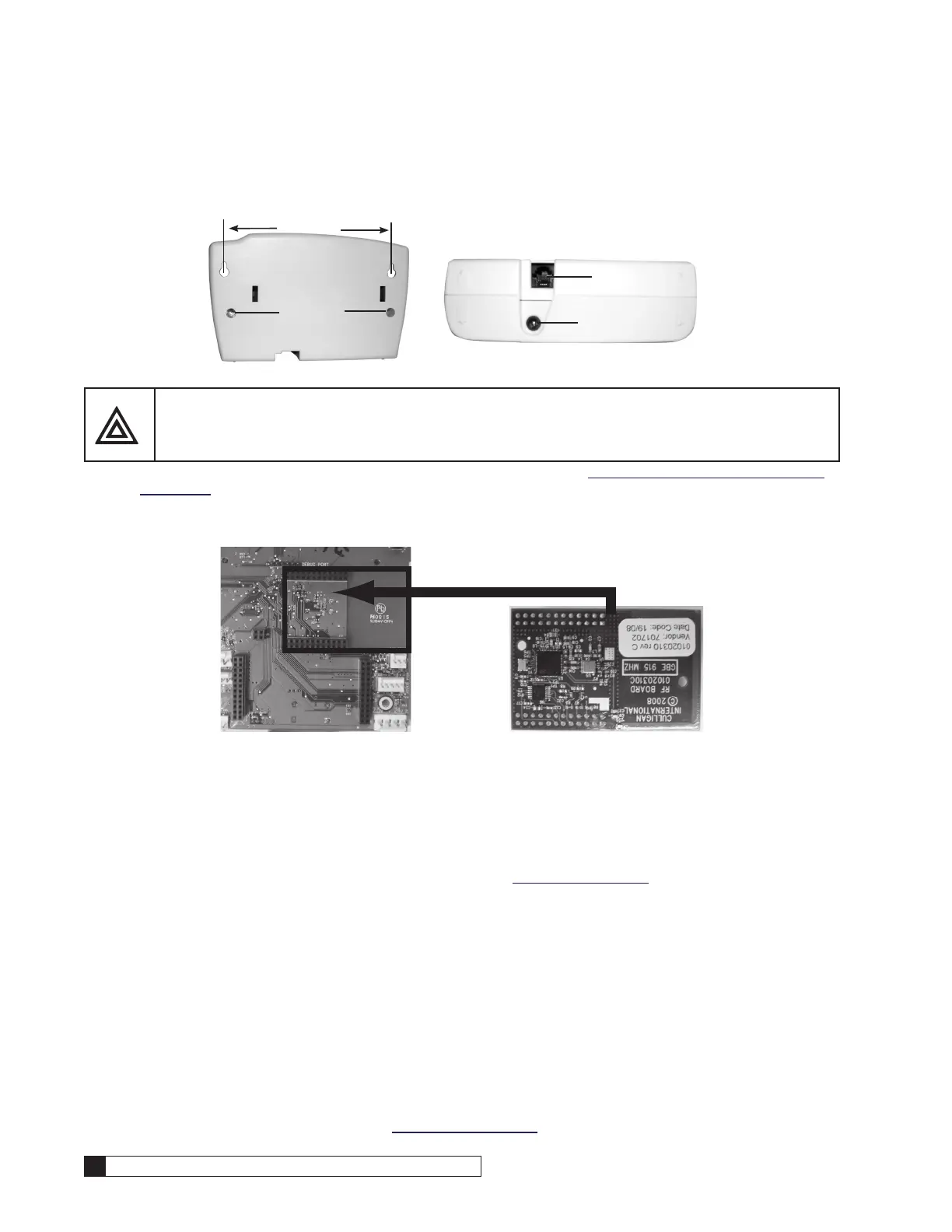
1. Select a location for the wireless remote monitor (Figure 51). The location must be near an electrical outlet. If a
modem is used in the remote, then the location should also be near a standard RJ-11 type telephone wall jack.
MODEM CONNECTION
POWER CONNECTION
SCREWS
Figure 51. Wireless remote monitor.
CAUTION! Do not touch any surfaces of the circuit board. Electrical static discharges may cause
damage to the board. Handle the circuit board by holding only the edges of the circuit
board. Keep replacement boards in their special anti-static bags until ready for use.
Mishandling of the circuit board will void the warranty.
2. (Optional) If a modem is to be installed into the remote monitor, refer to “Installing the Modem In the Remote”
on page 39 for installation and setup.
3. Connect the power cord to the bottom of the remote monitor. If a modem is to be used in the remote, plug a
standard telephone extension cord into the bottom of the remote monitor. Plug into 120V outlet.
4. Disconnect power to the softener. Open the control.
Back of GBE Board RF Board (note orientation)
Figure 52. RF board location on Smart Controller board.
5. Install RF board into unit controller. Line up pins in RF board and press firmly into black connectors. Note ori-
entation of RF board (see Figure 52). Make sure the RF board is fully seated into all of the sockets. Reconnect
power.
6. Program the remote and main monitor units using the instructions found in the GBE Programming for
Commercial Softeners and Filters (except for HFxN) Manual (P/N 01027295). This manual can be obtained from
your local dealer, Cport (www.cport.culligan.com) under the Technical Service Tab or the Service Tech App.
7. Place the remote monitor against the wall in the selected location, then check the signal strength. Refer to the
GBE Programming for Commercial Softeners and Filters (except for HFxN) Manual (P/N 01027295) for instruc-
tions.
8. Use the Hole Drilling Template (Figure 51) as a guide to drilling two holes to mount the remote monitor. If drill-
ing into wall board, drill two 5/16” diameter holes and insert the plastic drywall anchors into the holes securing
them with the two #10 screws provided. If drilling into a solid surface, drill two 7/32” holes into the surface and
screw the two #10 screws into the holes. In either case, leave a gap of approximately 3/32” between the head
of the screw and the wall. Hang the remote monitor on the two screws.
Smart Brine Tank Probe (P/N 01027289)
The Smart Brine Tank Probe Kit is not designed to work in a brine system taller than 40”. Refer to the Smart Brine Tank
(SBT) Probe Kit Manual (01026800) for installation instructions and the GBE Programming for Commercial Softeners and
Filters (except for HFxN) Manual (01027295) for programming instructions. This manual can be obtained from your local
dealer, CPort (www.cport.culligan.com) under the Technical Service Tab or on the Service Tech App.

 Loading...


