Installation 19
Cat. No. 01024821
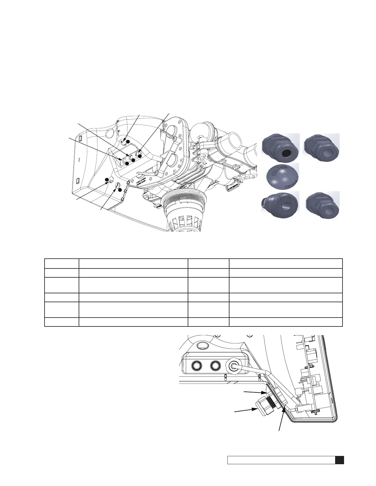
Installing Accessory Connections
The HE 1.5 Controller enclosure has several portals to allow connections to HE accessories. Each connection portal is
molded into the controller enclosure. If the portal is not already opened and/or plugged, it may be opened by pushing a
sharp object (screwdriver or knife) through the plastic. See Figure 21.
A connector/bushing and/or plug should be placed in the port assigned for each HE 1.5 accessory. See Figure 21 and
Figure 22 and Table 6 for connector/bushing and plug types and their position on the HE 1.5 Controller enclosure.
1
2
3
4
5
6
Figure 21. HE 1.5 Twin #1 Controller connection ports.
01025278 01024983
01025277
Figure 22. Connectors.
Table 6. Accessory connectors and possible connections.
Part No. Description Location(s) Connection
P1025274 Strain Relief Fitting, 10 PK 1 24V Power (pre-installed)
P1025264 Strain Relief Fitting, 10 PK 1, 2, 3 Aqua-Sensor, SBT, replaces 01025274
when used with optional 2.5VAC Power
P1025277 Liquid Tight Hole Plug, 10 PK 1, 2, 3, —
P1025278 Bushing, strain relief, 10 PK 4, 5 HE 1.5 Twin #2 Position Sensor, Harness,
HE 1.5 Twin #2 Motor Harness
— Cord Grip, Liquid Tight 4, 5, 6 Flow Meter Harness
To install an HE 1.5 accessory connection:
1. Remove the plastic plug from the port on
the enclosure, or open the port through
the molded recessed area.
2. Remove the plastic nut from the bushing
attached to the preinstalled connector
cable.
3. Place the bushing with the cable through
the port.
4. Tighten the nut on the interior side of the
port opening on the controller enclosure.
See Figure 23.
5. Attach the female connector to the Smart
Controller circuit board at the appropriate
location.
Nut Inside Controller Housing
Nut
Bushing
Figure 23. Connector bushing and nut position.
24V Power (also 2.5VAC
for optional Aqua-Sensor)
SBT
Motor Harness from Controller #2
Aqua-Sensor
Position Sensor Harness
form Twin Controller #2
Flow
Meter
Cable
 Loading...