Installation 17
Cat. No. 01024821
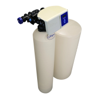
Brine System Installation
NOTE The brine system is purchased as an optional item to allow the use of various brine tank sizes to better
suit the needs of the user.
The softener system is normally regenerated using a timed brine refill, dry or wet salt storage brine system. To properly
install the brine system, set the brine tank assembly in a convenient location for ease of service and refill of salt into the
brine tank.
Brine Piping
The softeners can be used with a variety of brine systems. Please refer to Table 8 on page 35 for sizing parameters.
Position the salt storage tank in a convenient location on a smooth surface. The brine valve should be at the rear to sim-
plify removal of the tank cover.
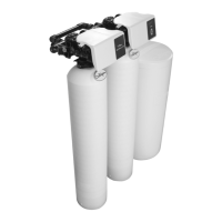
If multiple softeners will be drawing brine from the same tank, connect the brine tubing from the brine fitting on each valve
to a union tee. (P/N 00401574, supplied with small parts pack)
To Brine Line Adapter
Fitting Softener Unit
Duplex Tee
Polypro.
Insert
Nut
Tubing
To Brine Line Adapter
Fitting Softener Unit
Tubing
Nut- Plastic
Polypro. Insert
Brine Chamber
Cut 1/2” tubing (not supplied) sufficient to reach control using
brine fitting.
Brine Valve
Adjust float assembly to be just below the overflow fitting as a secondary
shut-off to the timed refill function of the GBE controller
Brine Connection Tubing
NOTE Culligan recommends routing the overflow
to the drain line or a floor drain to prevent
damage to the facility.
Circuit Board Connections
The 24V power supply and flow meter wire harness is already connected to the circuit board. If no other circuit board
connections are required proceed to the First Time Setup. Refer to the instructions below and Figure 17 to Figure 30 for
connecting accessories, including the Aqua-Sensor probe wire harness, to the circuit board.
WARNING! Disconnect all electrical power to the unit before connecting.
CAUTION! Grip all connections to the circuit board by the connecting terminals for assembly and
disassembly. Failure to do so could result in damage to the wire leads or connecting
terminals.
CAUTION! Do not touch any surfaces of the circuit board. Electrical static discharges might
cause damage to the board. Handle the circuit board by holding only the edges of the
circuit board. Mishandling of the circuit board will void the warranty.
NOTE Observe all state and local electrical codes.
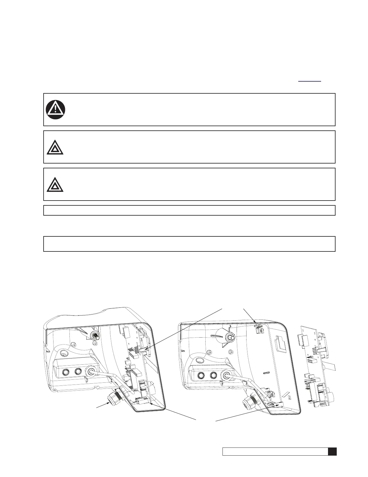
1. Remove the electrical enclosure from the control valve. First remove the electrical enclosure screw and then
gently remove the enclosure from the control. Refer to Figure 17 and Figure 18 and the following instructions.
NOTE The compartment plate is tightly connected to the enclsure and might be removed at the same time as
the enclosure.
2. Remove the compartment plate from the enclosure, placing the plate against the frame.
3. Disconnect the 24V power supply wire harness from the circuit board. See Figure 17.
4. Grip the circuit board from the edges and gently rotate it to the back of the enclosure (you are disengaging the
circuit board from the two support pins on the bottom and top of the enclosure). See Figure 18.
5. Remove the circuit board from the enclosure.
24 Volt Power Supply Cord
Support
Bracket
Support
Bracket
Figure 17. Circuit board power supply. Figure 18. Circuit board removal.
 Loading...