Note : Minimize the number of joint interactions
between the connecting rod and rod cap. There is only
a finite number of times a connecting rod and rod cap
can be assembled and removed before the joint loses
its proper interaction.
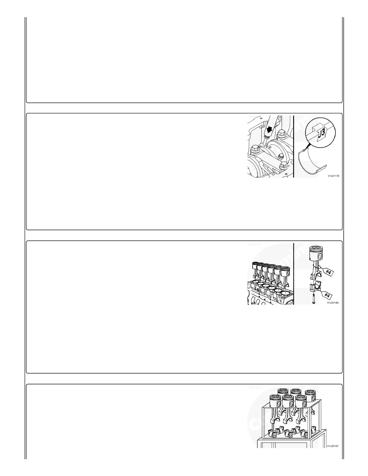
Remove the bearing shell from the rod cap and mark the
cylinder number and the letter "L” on the flat surface of the
bearing tangs.
Install two of the capscrews back into the rod hand-tight.
Use a T-handle piston pusher. Push only against the head of
the capscrew to push the rod up far enough to allow the upper
bearing shell to be removed.
DO NOT push against the fracture-split face of the rod.
Use caution not to scratch or damage the journal with the rod,
capscrew, or piston pusher.
Remove the bearing shell and mark the cylinder number and
the letter "U" on the flat surface of the bearing tangs.
Use both hands to remove the piston and connecting rod
assembly.
The piston and connecting rod assemblies must be installed in
the same cylinder from which they were removed to provide for
proper fit of worn mating surfaces if parts are reused.
Use a tag to mark the cylinder number from which each piston
and connecting rod assembly was removed.
Pistons that are reused must be installed in the same
orientation as when removed from the engine. Mark the front
side of the piston and piston pin with layout ink, or equivalent,
after removal.
Place the connecting rod and piston assemblies in a container
to protect them from damage.
The two pieces of the connecting rod can not be rubbed
together. This will damage the mating surfaces. Use care to
not drop either piece of the connecting rod. Fracture-split
 Loading...