EasyManua.ls Logo

Curt Manufacturing 16320 - User Manual

Curt Manufacturing 16320
9 pages
Print Icon
To Next Page IconTo Next Page
Loading...
CURTMFG.COM
NEED ASSISTANCE?
877.287.8 634
16320-INS-RA
PAGE 1
INSTALLATION MANUAL
16320
Tools Required
Ratchet Torque wrench
Socket set --
Product Photo
Torque Specifications
M8 bolt 16 ft-lbs.
M14 bolt 100 ft-lbs.
Use above torque setting unless otherwise noted
Product Registration
CURT Group stands behind our products
with industry-leading warranties. Provide
feedback and help us to improve our
products by registering your purchase at:
warranty.curtgroup.com/surveys
Level of Difficulty
Moderate
DANGER ZONE PRECAUTIONS
Block all trailer tires in front and behind with appropriate wheel chocks. Do not
substitute objects such as, but not limited to: stones, wood blocks, etc. Front
trailer lifting jacks must be supporting the trailer and resting on a firm and level surface.
Towing vehicle must be stationary with automatic transmission
in park (manual in neutral), emergency brake applied and engine off.
Parts List
Item Qty Description
1 1 Main body / Head assembly
2 2 Leg weldment
3 1 Handle assembly
4 1 Handle lock bar
5 2 Button head cap screw,
M8 - 1.25" x 30
6 2 Lock washer, M8
7 1 Latch spring
8 4 Hex bolt, M14
9 4 Lock washer, M14
10 4 Flat washer, M14
11 4 Nylock nut, M14
12 4 Base rail mounting clip
13 4 Base rail mounting pin, 1/2"
Weight Capacity
Gross trailer weight (GTW) 30,000 lbs.
Vertical load 7,500 lbs.
NOTICE
Before you begin installation,
read all instructions thoroughly.
Proper tools will improve the quality of
installation and reduce the time required.
To help prevent damage to the product
or vehicle, refer to the specified torque
specifications when securing hardware
during the installation process.
WARNING
Fully instruct and demonstrate the operation of this 5th wheel hitch to the end user. Include the
importance of observing all warnings contained herein, including warning labels on 5th wheel
hitch main body. Provide this manual in its entirety to the end user. Serious injury or death may
result if the warnings above are not observed.
Do not expose hands, body parts or clothing between the truck and
trailer or the truck's bed sides and trailer. If you must place any part
of your body under trailer or between truck and trailer, you must:
1. Block all trailer tires with wheel chocks.
2. Make sure trailer landing gear / jacks are resting on a firm, level surface.
3. Towing vehicle must be stationary with auto transmission in park
(manual in neutral), emergency brake applied and engine off.
Never exceed the towing capacity (trailer and contents combined)
of any towing system component or your vehicle.
Improperly coupled trailers can separate or drop without notice,
causing serious injury or death. To reduce the chance of serious injury or death:
Never attempt to couple trailer without reading and following all instructions thoroughly.
Always follow operating instructions to secure trailer to tow vehicle.
Make sure the hitch is secure before towing.
Prior to towing, ensure all components and hardware are structurally sound and secure.
Always chock the trailer to prevent movement while coupling the hitch.
Always ensure lynch pins are installed through handle and center pivot pin before towing.
Always keep hands clear of the 5th wheel jaws when operating the handle.
Always perform a pull test prior to towing. See 'pull test' later in this instruction manual.
Never position anyone under the trailer's kingpin area during coupling and uncoupling.
Question and Answer IconNeed help?

Do you have a question about the Curt Manufacturing 16320 and is the answer not in the manual?

Summary

Safety Information

Danger Zone Precautions

Block trailer tires, ensure vehicle stationary, applied brakes, and engine off.

Operational Warnings

Instruct end user, keep hands clear of jaws, never exceed capacity, ensure proper coupling.

Installation Guide

Calculating Height

Measure trailer kingpin box height and truck bed height to determine optimal 5th wheel head alignment.

Main Body Assembly

Assemble the legs to the main body, ensuring correct height adjustment for the 5th wheel head.

Base Rail Installation

Check base rail alignment, measure diagonals, and secure rails according to manufacturer specs.

Handle Assembly

Assemble the handle, latch spring, and lock bar to the 5th wheel head.

Coupling and Locking

Preparing for Coupling

Ensure trailer and vehicle are level, align kingpin, check jaws are open and unlocked.

Coupling Procedure

Back up vehicle, align kingpin, confirm jaws lock, and install safety pin.

Uncoupling and Resetting

Uncoupling Procedure

Park vehicle, chock trailer wheels, disconnect, extend jacks, unlock handle, and pull vehicle away.

Remove & Reinstall

Removal Options

Describes two methods to remove the 5th wheel hitch from the base rails.

Re-installation

Details the steps for reinstalling the 5th wheel hitch in the reverse order of removal.

Maintenance

Maintenance Schedule

Outlines regular checks and lubrication for wear plates, pivot points, jaws, and linkage.

Overview

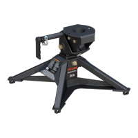
This document is an installation and maintenance manual for a CURT PowerRide 30K 5th wheel hitch, model number 16320.

Function Description:

The CURT PowerRide 30K 5th wheel hitch is designed to provide a secure and reliable connection between a towing vehicle and a 5th wheel trailer. It facilitates the coupling and uncoupling process, ensuring safe towing by securely engaging the trailer's kingpin. The hitch features an integrated wear plate system that eliminates the need for traditional grease, simplifying maintenance. Its design allows for height adjustment to accommodate various truck bed and trailer configurations, ensuring the trailer rides as level as possible. The hitch incorporates visual indicators (green, red, yellow) to clearly communicate its locked, unlocked, and coupled status, enhancing user safety and operational clarity.

Important Technical Specifications:

  • Model Number: 16320
  • Gross Trailer Weight (GTW): 30,000 lbs.
  • Vertical Load: 7,500 lbs.
  • Adjustable Height: 13" to 17" (from truck bed to top of skid plate), adjustable in 1.25" increments.
  • Minimum Clearance: 5-1/2" between truck bed rails and trailer.
  • Hardware Torque Specifications:
    • M8 bolts: 16 ft-lbs.
    • M14 hex bolts: 100 ft-lbs.
    • 16mm head pivot bolts: 175 ft-lbs.
  • Components: Main body/head assembly, leg weldments, handle assembly, handle lock bar, various screws, washers, nuts, latch spring, base rail mounting clips, and pins.

Usage Features:

  • Assembly: The manual provides detailed steps for assembling the main body, leg weldments, and handle. It emphasizes determining the correct height adjustment based on the trailer's kingpin box skid plate and the truck bed surface.
  • Height Calculation: A three-step process is outlined to measure and calculate the required hitch height, ensuring optimal trailer leveling and adequate clearance.
  • Coupling & Locking:
    • Preparation: Requires chocking trailer wheels, ensuring a firm and level surface, and positioning the tow vehicle with the trailer kingpin approximately 4" from the hitch's skid plate and 1/2" below the lead-in ramp.
    • Visual Indicators: The hitch uses a GREEN indicator (circle) for a locked handle, a RED indicator (octagon) for an unlocked handle, and a YELLOW indicator (triangle) for a coupled handle. These indicators are crucial for verifying the hitch's status from the cab.
    • Unlocking: Involves removing the safety latch pin, pulling the handle out, and swinging it forward until it latches in the unlocked position, displaying the YELLOW indicator.
    • Coupling Process: Backing up the tow vehicle to allow the trailer's kingpin skid plate to compress the suspension and ramp onto the 5th wheel skid plate. The kingpin must fully seat into the opening, and the YELLOW indicator should change to GREEN, with the handle swinging rearward to the locked position.
    • Pull Test: Mandatory after coupling to confirm 100% engagement by lightly tugging the tow vehicle forward.
    • Safety Pin: Must be inserted through the locking handle after coupling to prevent unintentional unlocking.
  • Uncoupling & Resetting:
    • Preparation: Chocking trailer wheels, disconnecting harnesses, and extending trailer lifting jacks to remove weight from the 5th wheel skid plate.
    • Unlocking: Removing the safety lynch pin, pulling the handle out, and swinging it forward until it latches in the unlocked position (RED indicator visible).
    • Separation: Slowly driving the tow vehicle out from under the trailer. The handle will drop back to the couple position (YELLOW indicator) once the kingpin is clear.
  • Removal & Reinstallation: Two options are provided for removing the hitch from the base rails: removing the entire unit or separating the head from the main body first. Reinstallation follows the reverse order.

Maintenance Features:

The manual outlines a comprehensive maintenance schedule to ensure years of safe and reliable service:

  • Integrated Wear Plates: Inspect before each use and every 1,000 miles. Replace if grooves are worn flush (CURT# 19269). A lube plate (CURT# 16722) can be used on the trailer's kingpin to reduce wear.
  • Center Pivot Point: Lubricate before each use with high-pressure wheel bearing grease after removing the pin.
  • M14 Hex Bolts: Torque to 100 ft-lbs before each use and every 1,000 miles. Re-torque after initial 500 miles.
  • 16mm Head Pivot Bolts: Torque to 175 ft-lbs before each use and every 1,000 miles.
  • Locking Pawl: Lubricate before each use by applying a small amount of grease to the curved surface, accessible through the operating handle opening.
  • Jaw Pivot Point: Lubricate every 3,000 miles using a grease gun on the zerks located on the front of each jaw (jaws must be closed and locked).
  • Linkage Pivot Points: Lubricate before each use with an aerosol rust inhibitor or lubricant on the lock handle, linkage bar, and pawl pivot points.
  • Head Pivot Points: Lubricate every 3,000 miles using a grease gun on the zerks located on both sides of the head.
  • Cleaning: Clean the 5th wheel hitch after each use with warm soapy water and dry thoroughly. For long-term storage, remove the hitch from the vehicle or cover it, and spray exposed surfaces with a light coat of rust inhibitor.

Safety Precautions:

The manual includes critical "DANGER ZONE PRECAUTIONS" and "WARNING" sections, emphasizing:

  • Blocking trailer tires with wheel chocks.
  • Ensuring the towing vehicle is stationary with the emergency brake applied and engine off.
  • Never exceeding towing capacity.
  • Avoiding exposure of hands/body parts between the truck and trailer.
  • Never attempting to couple without thoroughly reading instructions.
  • Ensuring the hitch is secure before towing.
  • Keeping hands clear of 5th wheel jaws during operation.
  • Performing a pull test before towing.
  • Never positioning anyone under the trailer's kingpin area during coupling/uncoupling.
  • Addressing red indicator/jaws open issues before towing.
  • Not towing if the kingpin is not properly coupled and the safety pin is not installed.
  • Not attempting to couple in any configuration other than the yellow couple position.

Curt Manufacturing 16320 Specifications

General IconGeneral
BrandCurt Manufacturing
Model16320
CategoryAutomobile Accessories
LanguageEnglish

Related product manuals