EasyManua.ls Logo

Curt Manufacturing 16600 - User Manual

Curt Manufacturing 16600
8 pages
Print Icon
To Next Page IconTo Next Page
Loading...
CURTMFG.COM
PRODUCT SUPPORT: 877.287.8634
16600-INS-RA
12/08/2021
ECN9081
PAGE 1
INSTALLATION MANUAL
16600
Tools Required
Ratchet Torque wrench
Socket set --
Product Photo
Torque Specifications
1/2" bolt 65 ft-lbs.
M20 bolt 300 ft-lbs.
Use above torque setting unless otherwise noted
Product Registration
CURT stands behind our products with
industry-leading warranties. Provide
feedback and help us to improve our
products by registering your purchase at:
warranty.curtgroup.com/surveys
Level of Difficulty
Moderate
DANGER ZONE PRECAUTIONS
Block all trailer tires in front and behind with appropriate wheel chocks. Do not
substitute objects such as, but not limited to: stones, wood blocks, etc. Front
trailer lifting jacks must be supporting the trailer and resting on a firm and level surface.
Towing vehicle must be stationary with automatic transmission
in park (manual in neutral), emergency brake applied and engine off.
Parts List
Item Qty Description
1 1 Base weldment
2 1 Upper weldment
3 1 Lower coupler assembly
4 1 Lube plate
5 2 Hex head cap screw, 1/2"
6 2 Nylock nut, 1/2"
7 1 Bushing
8 1 Hex bolt, M20
9 1 Nylock nut, M20
10 1 Flat washer, M20
11 4 Spacer, 0.094"
12 4 Base rail mounting clip
13 4 Base rail mounting pin, 1/2"
Weight Capacity
Gross trailer weight (GTW) 20,000 lbs.
Vertical load 5,000 lbs.
NOTICE
Before you begin installation,
read all instructions thoroughly.
Proper tools will improve the quality of
installation and reduce the time required.
To help prevent damage to the product
or vehicle, refer to the specified torque
specifications when securing hardware
during the installation process.
WARNING
Fully instruct and demonstrate the operation of this 5th wheel hitch to the end user. Include the
importance of observing all warnings contained herein, including warning labels on 5th wheel
hitch main body. Provide this manual in its entirety to the end user. Serious injury or death may
result if the warnings above are not observed.
Do not expose hands, body parts or clothing between the truck and
trailer or the truck's bed sides and trailer. If you must place any part
of your body under trailer or between truck and trailer, you must:
1. Block all trailer tires with wheel chocks.
2. Make sure trailer landing gear / jacks are resting on a firm, level surface.
3. Towing vehicle must be stationary with auto transmission in park
(manual in neutral), emergency brake applied and engine off.
Never exceed the towing capacity (trailer and contents combined)
of any towing system component or your vehicle.
Improperly coupled trailers can separate or drop without notice,
causing serious injury or death. To reduce the chance of serious injury or death:
Never attempt to couple trailer without reading and following all instructions thoroughly.
Always follow operating instructions to secure trailer to tow vehicle.
Make sure the hitch is secure before towing.
Prior to towing, ensure all components and hardware are structurally sound and secure.
Always chock the trailer to prevent movement while coupling the hitch.
Always ensure lynch pins are installed through handle before towing.
Always perform a pull test prior to towing. See 'pull test' later in this instruction manual.
Never position anyone under the trailer's kingpin area during coupling and uncoupling.
Question and Answer IconNeed help?

Do you have a question about the Curt Manufacturing 16600 and is the answer not in the manual?

Summary

Danger Zone Precautions

Warnings and Important Notices

General Warnings

Instructions and warnings regarding safe operation and potential hazards of the 5th wheel hitch.

Product Registration and Notice

Information on product registration and general installation notices for proper setup.

Assembly and Height Calculation

Calculating Height

Determining the correct 5th wheel height for level trailer towing by measuring distances.

Main Body Assembly

Instructions for assembling the main body of the 5th wheel hitch.

Main Body Assembly Steps

Lower Coupler Attachment

Attaching the lower coupler assembly to the base weldment using specified fasteners.

Check the Base Rails

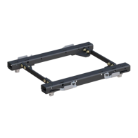
Verifying the proper installation and alignment of truck bed base rails.

Mount to the Base Rails

Securing the 5th wheel hitch to the vehicle's base rails using pins and clips.

Upper Coupler Installation

Step 1: Component Placement

Placing upper weldment and lube plate on trailer king pin and securing with bolts.

Step 2: Torque Specification

Torquing the 1/2" hex bolts and nuts to the specified torque value.

Step 3: Free Spin Check

Ensuring the upper weldment spins freely around the trailer's king pin.

Coupling and Locking Procedures

Coupling Warnings

Safety precautions to avoid injury or death during coupling operations.

Prepare Vehicle and Trailer

Steps to prepare the truck and trailer for coupling on a level surface.

Prepare 5 th Wheel Hitch

Ensuring the 5th wheel hitch mechanism is clean and ready for coupling.

Perform Coupling and Locking

Detailed steps for coupling the trailer to the hitch and securing the lock.

Pre-Tow Checks and Uncoupling

Pull Test Procedure

Testing the secure coupling of the hitch by applying light forward pressure.

Preparing to Tow Checklist

Final checks before towing, including electrical connections and brake activation.

Uncoupling Steps

Procedure for safely uncoupling the trailer from the 5th wheel hitch.

Removal and Reinstallation

Removal Procedure

Steps to remove the entire 5th wheel hitch unit from the base rails.

Re-installation Procedure

Instructions for reinstalling the 5th wheel hitch in reverse order of removal.

Maintenance Schedule

Component Inspection and Lubrication

Regular checks for lube plate, pivot points, and bolts for optimal performance.

Cleaning and Storage

Recommendations for cleaning the hitch after use and before long-term storage.

Torque and Bolt Warning

Critical warning regarding the torque of the M20 head pivot bolt and potential failure.

Overview

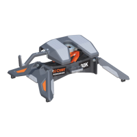
This document outlines the installation, operation, and maintenance of a CURT 5th wheel hitch, designed for towing trailers. The hitch is a robust device that connects a fifth-wheel trailer to a towing vehicle, ensuring a secure and stable connection for safe transport. It is engineered to provide years of reliable service when properly installed, operated, and maintained according to the instructions provided.

Function Description

The primary function of the CURT 5th wheel hitch is to create a secure coupling between a towing vehicle and a fifth-wheel trailer. This is achieved through a multi-component assembly that includes a base weldment, an upper weldment, and a lower coupler assembly. The hitch is designed to accommodate various trailer and vehicle setups by offering adjustable height settings, ensuring the trailer rides as level as possible. This adjustability is crucial for maintaining proper towing dynamics and preventing undue stress on both the towing vehicle and the trailer. The hitch's locking mechanism is a critical safety feature, designed to firmly secure the trailer's kingpin, preventing accidental uncoupling during transit. The system also incorporates features to facilitate the coupling and uncoupling processes, making them as straightforward and safe as possible for the user. Safety is paramount, with explicit warnings and precautions detailed throughout the manual to prevent serious injury or death, emphasizing the importance of proper procedures, equipment, and awareness of the "danger zone" around the coupling area.

Usage Features

The CURT 5th wheel hitch is designed with several usage features to enhance safety, ease of operation, and adaptability.

  • Adjustable Height: A key feature is its adjustable height, ranging from 16-3/8" to 20-3/8" from the truck bed rails to the top of its skid plate. This adjustability is achieved by modifying the lower coupler assembly's position in 2" increments relative to the base weldment. This allows users to achieve an optimal, level ride for their trailer, which is essential for stability and tire wear. The manual provides a detailed three-step process for calculating the required height, involving measurements from the ground to the trailer's kingpin box skid plate and from the ground to the truck bed rails.
  • Main Body Assembly: The main body assembly involves attaching the lower coupler assembly to the base weldment using specific fasteners. The bushing must be installed correctly and oriented towards the rear of the vehicle. Torque specifications for the M20 bolt and nut are provided (300 ft-lbs) to ensure a secure connection. Before mounting the hitch to the base rails, the manual emphasizes checking that the base rails in the truck are properly installed and parallel, with diagonal measurements being equal. If new base rails are being installed, users must follow the rail manufacturer's instructions for placement, alignment, and spacing. For existing base rails, realignment may be necessary, and old lock washers should be replaced with new ones.
  • Mounting to Base Rails: The hitch is designed to drop into slots on the top surface of the base rails, aligning four tabs on the bottom of the hitch legs with corresponding slots in the tow vehicle's base rails. It is then secured with four 1/2" rail mount pins and clips. Optional neoprene spacers can be used between the hitch and the rails to reduce clanking and rattling, improving the towing experience.
  • Upper Coupler Installation: The upper weldment and lube plate are placed on the trailer kingpin. While holding the upper weldment tight against the pin box, two 1/2" hex bolts are inserted through the upper weldment and secured with 1/2" nylock nuts. These bolts are torqued to 65 ft-lbs. After installation, it's crucial to ensure the upper weldment spins freely around the kingpin, indicating proper installation.
  • Coupling & Locking Process: The manual provides a comprehensive guide for coupling and locking the trailer. This process begins with preparing the 5th wheel by ensuring the locking mechanism is free of debris and properly lubricated. The vehicle and trailer must be on a firm, level surface, with multiple wheel chocks used. The trailer's coupler should be positioned approximately 1" above the hitch head. The safety pin is removed, the handle pushed in and turned counterclockwise to allow coupling. The tow vehicle is then slowly backed until the trailer coupler contacts the hitch face and seats fully. The handle is then pushed in and turned clockwise to the locked position, and the safety pin is re-inserted. A crucial "pull test" is mandated after coupling to confirm a 100% secure connection.
  • Uncoupling & Resetting Process: Uncoupling involves parking on a firm, level surface, chocking trailer wheels, disconnecting all harnesses, and extending the front trailer lifting jacks to remove weight from the 5th wheel skid plate. The safety pin is removed, the handle pushed in and turned counterclockwise, then pulled out completely. The jacks are lowered until the trailer coupler clears the hitch coupler. Finally, the parking brake is removed, and the tow vehicle is slowly driven out from under the trailer.
  • Removal & Reinstallation: The hitch can be removed from the base rails by removing the base rail pins and clips. Reinstallation follows the reverse order of removal.
  • Safety Precautions: Throughout the manual, significant emphasis is placed on safety. "Danger Zone Precautions" include blocking trailer tires, ensuring front trailer lifting jacks support the trailer on a firm surface, and having the towing vehicle stationary with the emergency brake applied and engine off. "Warnings" highlight the importance of fully instructing end-users on hitch operation, never exceeding towing capacity, and the risks of improper coupling. Users are explicitly warned not to position themselves or others under the trailer's kingpin area during coupling and uncoupling.

Maintenance Features

To ensure the CURT 5th wheel hitch provides years of safe and reliable service, the manual outlines a detailed maintenance schedule.

  • Inspect Lube Plate: The lube plate (#1) should be inspected before each use and every 1,000 miles. If worn, it should be replaced with CURT# 16722. This ensures smooth operation and reduces wear between the kingpin and the hitch head.
  • Lubricate Head Pivot Point: The head pivot point (#2) requires lubrication before each use with a light dry film lubricant. This prevents rust and ensures the pivot mechanism operates smoothly.
  • Torque 1/2" Bolts: The two 1/2" hex bolts (#3) should be torqued to 65 ft-lbs every 1,000 miles. An initial re-torque is recommended after the first 500 miles. Maintaining proper torque on these bolts is critical for the structural integrity of the hitch.
  • Handle Pin: The handle pin (#4) should be sprayed with a light dry film lubricant before each use. This ensures the handle operates freely for coupling and uncoupling.
  • Torque Lower M20 Bolt: The lower M20 bolt (#5) should be torqued to 300 ft-lbs before each use and every 1,000 miles. This bolt is crucial for securing the lower coupler assembly to the base weldment.
  • Clean 5th Wheel Hitch: For optimal service life, the 5th wheel hitch should be cleaned after each use with warm soapy water and dried with towels or compressed air. This prevents the buildup of dirt and grime that could impede operation.
  • Long-Term Storage: When not in use for extended periods, it is recommended to remove the 5th wheel from the vehicle or cover it. Exposed surfaces should be sprayed with a light coat of rust inhibitor to prevent corrosion.
  • M20 Head Pivot Bolt Warning: A specific warning is issued regarding the upper M20 head pivot bolt (#6) nut. It is designed only to make contact and not apply clamping force. Torquing this bolt could cause it to fail, leading to hitch separation and severe injury or death. If the hitch head appears loose, the 20mm bolt should be removed and inspected for damage; any visible cracks or damage necessitate immediate discontinuation of hitch use.

These maintenance steps are designed to prolong the life of the hitch, ensure its safe operation, and prevent potential failures that could lead to serious accidents. Adherence to these guidelines is essential for all users of the CURT 5th wheel hitch.

Curt Manufacturing 16600 Specifications

General IconGeneral
Product TypeGooseneck Hitch
BrandCurt Manufacturing
Part Number16600
CategoryAutomobile Accessories
Weight Capacity30, 000 lbs
Tongue Weight7, 500 lbs
MaterialSteel
InstallationVehicle-Specific
FinishBlack Powder Coat
Hitch Pin Hole Size5/8 inches

Related product manuals