2 — INSTALLATION AND WIRING
pg. 11
Return to TOC 1212 & 1212P Manual - Sep 2019
Battery Discharge Indicator (BDI)
e 1212/1212P controller can drive a BDI panel meter to show the battery pack’s state of charge as
a percentage of the ampere-hour capacity of the batteries. e batteries must be put through a full
charge cycle with the controller installed before the BDI will begin operation.
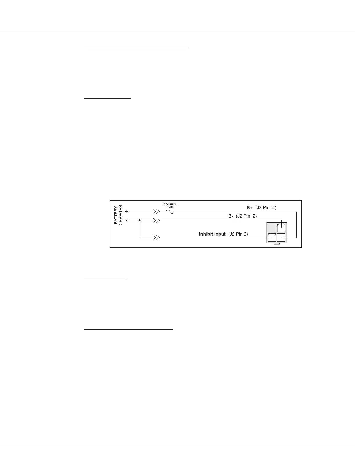
Charger Inhibit
Typically, battery chargers have a dedicated third terminal that automatically provides inhibit. When
the charger is connected to the controller’s J2 connector, the controller disables the drive functions
and engages the EM brake while the charger is connected. Inhibit is provided through J2 Pin 3; see
wiring diagrams (Figure 3a, page 6, and Figure 3b, page 7). e charger inhibit automatically powers
up the controller without the keyswitch on so that BDI can be tracked during charge. Aer BDI is
100% reset, power is totally shut o (no current used) to avoid draining the battery.
If your battery charger does not have a dedicated inhibit terminal, you must wire B– to J2 Pin 3, as
shown in Figure 6.
For pallet truck applications, the charger B+ and B- should not connect to J2 due to its low current
rating, as shown in Figure 3b.
1 2
34
Figure 6
Wiring to Inhibit
Operation During
Battery Charging
(For Battery Chargers
Without a Dedicated
Inhibit Terminal).
Speed Inhibit
A speed inhibit switch can be used to limit drive speed, or even to prevent drive altogether, in certain
conditions; see Inhibit menu. e maximum speed allowed during inhibit operation is also set in the
Inhibit menu, with a setting of zero preventing drive.
Circuitry Protection Devices
To protect the control wiring from accidental shorts, a low current fuse (appropriately sized for the
maximum control circuit current draw) should be connected in series with the B+ logic supply. A
fuse is also recommended in the high power circuit from the battery to the controller’s B+ terminal.
is fuse will protect the power system from external shorts and should be sized appropriately for
the maximum rated current of the controller.