Curtis PMC 1209B/1221B/1221C/1231C Manual
7
HARDWARE INSTALLATION
5kΩ–0 Input
The 1209B/1221B/1221C/1231C controllers are also available with 5kΩ–0
throttle inputs. Using this throttle type, controller output begins at ≈4400 ohms
with full output at less than 300 ohms.
0–5V Input
A 0–5V throttle input option is also available for these controllers. The negative
side of the 5V source should be referenced to B- and must be capable of driving
an input impedance of 5kΩ.
Curtis offers two bi-directional, wigwag electronic throttle assemblies de-
signed for use with the 0–5V input: the ET series and the CH series. They
require a 24–36V supply voltage.
The ET-XXX throttle assembly provides a 0–5V output and forward/reverse
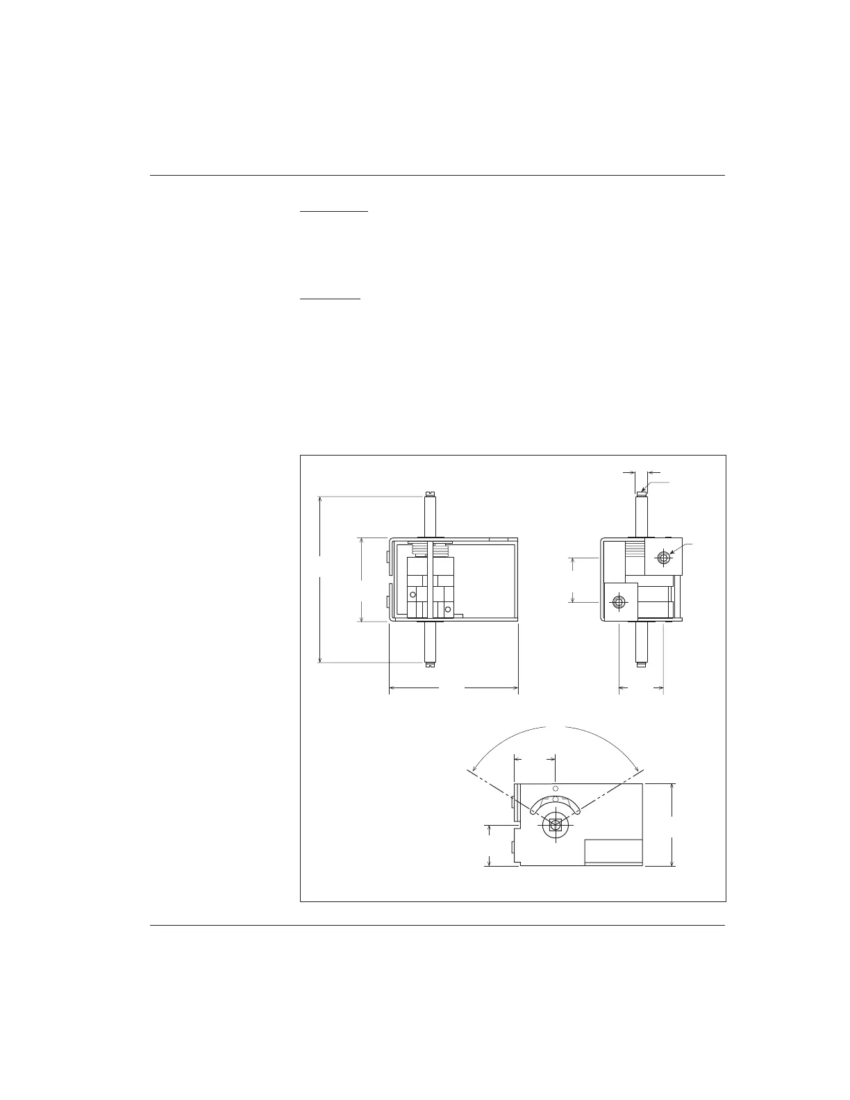
relay coil drivers. Dimensions for the ET-series throttles are shown in Figure 6.
Dimensions in millimeters and (inches)
99
(3.90)
44
(1.73)
69
(2.72)
24
(0.94)
VIS TC 3×12
6
×
6 (0.24
×
0.24)
24
(0.94)
∅ M5
22
(0.87)
22
(0.87)
116
°
44
(1.73)
Fig. 6 Mounting
dimensions,
Curtis electronic throttle
(ET series).



 To Next Page