Curtis PMC 1209B/1221B/1221C/1231C Manual
14
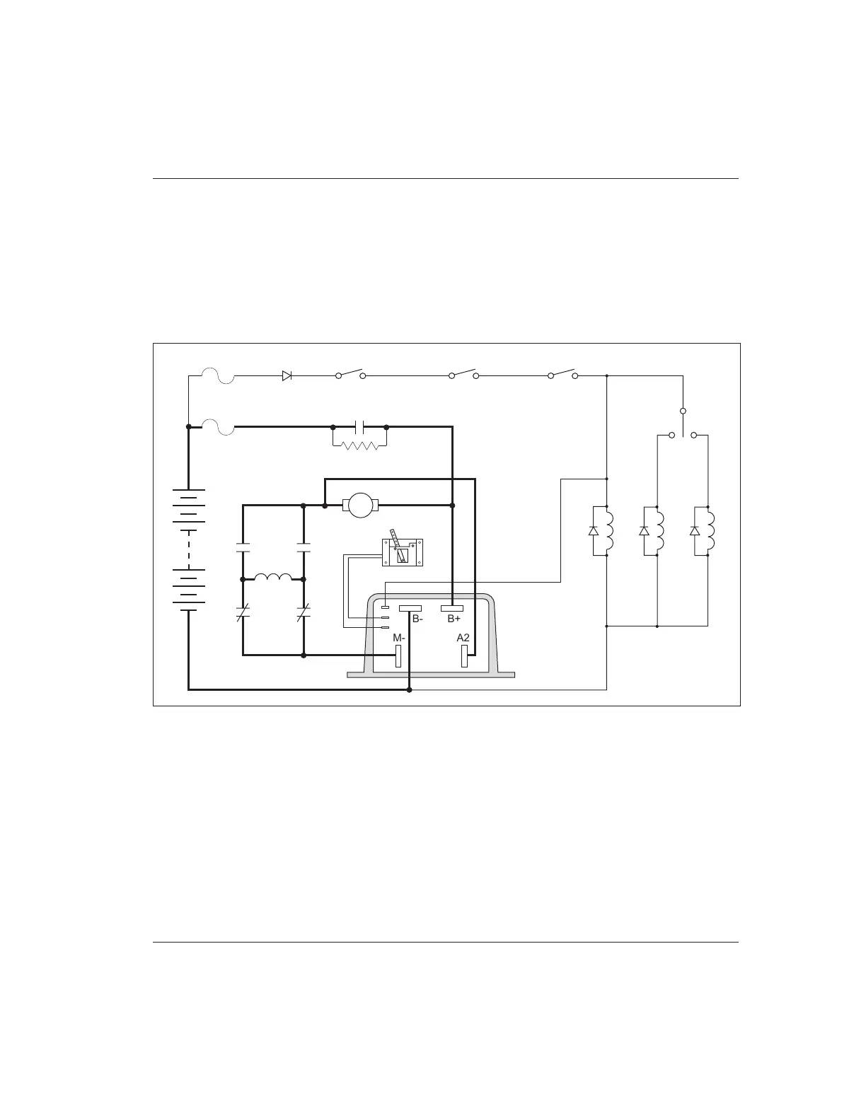
WIRING: TYPICAL INSTALLATION
Figure 9 is a schematic diagram of the typical 1209B, 1221B, and 1221C
installation shown in Figure 7. Wired this way, the vehicle will plug brake if the
direction is changed with the vehicle moving and the throttle applied. Reversing
is accomplished via a forward/reverse changeover contactor or two single-pole,
double-throw (2×SPDT) contactors. Coil suppression diodes should be used on
the main and forward/reverse contactors.
WIRING
Fig. 9 Basic wiring configuration, Curtis PMC 1209B/1221B/1221C controllers.
A2M-
B-
B+
+
–
FORWARD
REVERSE
MAIN
F R
S2
A2
S1
A1
F
R
F
R
POTBOX
MAIN
KEYSWITCH INTERLOCKS
THROTTLE
MICROSWITCH
CONTROL WIRING
FUSE
POLARITY
PROTECTION
DIODE
PRECHARGE RESISTOR
POWER WIRING
FUSE