Curtis PMC 1209B/1221B/1221C/1231C Manual
20
WIRING
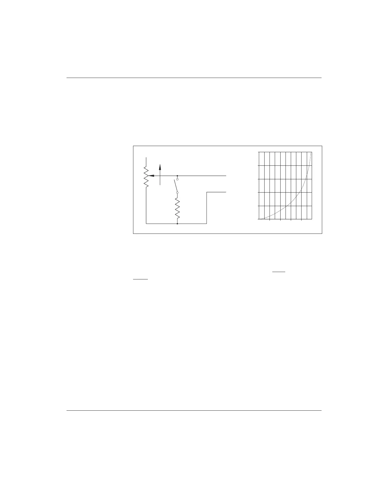
Fig. 15 Reduced speed
operation (with standard
0–5k
Ω
pot).
Reduced Speed Operation
Vehicle top speed can be easily limited, for safety or other reasons. A single resistor
connected in parallel with the throttle pot will reduce maximum speed according
to its resistance value, as shown in Figure 15. Use of a variable resistor makes
adjustment of maximum speed easier. With a switch, speed can be limited in
reverse only, or the speed reduction can be switched off—for example, to allow
authorized personnel to run the vehicle outdoors at full speed.
The speed reduction shown in the curve is approximate. The actual vehicle
top speed will depend on the motor characteristics and the vehicle load. You
should determine by experiment the proper resistor value to give the desired speed
reduction. (NOTE: With reduced speed operation, only top speed is reduced; full
power is maintained for starting at low speeds.)
Unlike resistor controllers, Curtis PMC controllers operate efficiently in the
reduced speed mode, because little power is lost through the controller.
TO
THROTTLE
INPUT
SPEED
REDUCTION
RESISTOR
FASTER
OPTIONAL
SWITCH
SPEED REDUCTION RESISTOR
(k ohms)
APPROX. % OF ORIGINAL TOP SPEED
0 20 40 60 80 100
25
20
15
10
5
0
0–5kΩ POT