
C
Cindy FullerAug 2, 2025
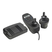
What to do if my Curtis enAble 40 Control Systems joystick is out of range?
- MMichael BlakeAug 2, 2025
If you are experiencing a joystick fault with your Curtis Control Systems, such as the joystick being out of range, try the following: Return the joystick to its neutral position and cycle the power. If the problem persists, recalibrate the joystick. Also, inspect the joystick cable and its connections for any issues. If none of these steps resolve the problem, consider replacing the joystick or the hand control.