10
Curtis enAble
®
40 Manual, Rev. E
1741
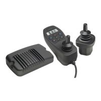
HANDCONTROL
1740 POWERBASE
1742
ATTENDANT
CONTROL
1740 POWERBASE
Pin 1 B+
Pin 2 B-
Pin 3 Inhibit (active to ground/B-)
Pin 4 TXD
Pin 5 RXD
2 — INSTALLATION & WIRING
CONNECTING THE CONTROL MODULES
The communications cable on the 1741 user handcontrol and on the 1742
attendant control each terminate in a plug that fits into the powerbase’s 6-pin
connector. The attendant control’s cable includes a Y-junction into which the
user handcontrol’s cable connects, as shown in Figure 7.
5-pin charger/programmer port
The user handcontrol has a 5-pin port that accommodates a battery charger and
a programmer (although not at the same time). The charger plug’s three pins
fit into sockets 1, 2, and 3. The programmer plug’s two pins fit into sockets 4
and 5. Both plugs are designed to snap securely into the port.
Allowable current for a charger in this port is 8 amps continuous.
The inhibit pin (pin 3) halts all chair travel during charging. Additionally,
it can prevent specific actuator movements.
Fig. 7 Connecting the
control modules to the
powerbase.
(view looking
into the port)