Curtis enAble
®
40 Manual, Rev. E v
FIGURES
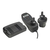
FIG. 1: Curtis enAble
®
40 Powerchair Control System ....................... 1
FIG. 2: Mounting dimensions, 1740 powerbase .................................. 5
FIG. 3: Mounting dimensions, 1741 user handcontrol ......................... 6
FIG. 4: Mounting dimensions, 1742 attendant control ........................ 7
FIG. 5: Basic wiring diagram, 1740 powerbase ..................................... 8
FIG. 6: Wiring for the Multi-Function inputs ...................................... 9
FIG. 7: Connecting the control modules to the powerbase ................. 10
FIG. 8a: Handcontrol: Drive-Only keypad .......................................... 12
FIG. 8b: Handcontrol: Drive + Lights keypad ...................................... 13
FIG. 8c: Handcontrol: Drive + Actuators keypad ................................. 14
FIG. 8d: Handcontrol: Drive + Actuators + Lights keypad ................... 15
FIG. 9: Handcontrol: LCD display icons ........................................... 16
FIG. 10: Attendant control module ...................................................... 17
FIG. 11: Electronic gating,
using the Gate Shape parameter ............................................. 23
FIG. 12: Dynamic turn radius control,
using the Speed Full Turn and Speed No Turn parameters .....
23
TABLES
TABLE 1: Handcontrol (1741) diagnostics ........................................... 48
TABLE 2: Attendant control (1742) diagnostics ................................... 51
TABLE E-1: Specifications, 1740 powerbase ...........................................E-1
TABLE E-2: Specifications, 1741 handcontrol ........................................E-1
TABLE E-3: Specifications, 1742 attendant control ................................E-1
FIGURES / TABLES