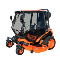
CAB INSTALLATION
19 of 35
Fig. 7.10 (Install Switch Bracket)
Bolt
Fig. 7.7 (Attach Red Wires to Battery)
Fig. 7.8 (Route Harness to Right Control Stick)
Fig. 7.9 (Connect Wires to Switch)
Take Image During Pilot Install
M6 Nut
7.7 See fig. 7.7. Install the ring terminals on the red
wires from both the main harness and from the
regulator power harness onto the stud on the
positive battery clamp (outboard of the existing
battery clamp nut) and secure with the following
hardware.
Hardware Used Qty
M6x1.0 Nut 1
7.8 See fig. 7.8. Locate the portion of the wire harness
with two ring terminals crimped on the ends of
black and gray wires. Route the ring terminals
forward over the ROPS tube in front of the battery
next to the existing wiring and up along the right
side of the vehicle to right hand control.
Note: Wires must be routed above the ROPS, but
below the flat area that the hood seals on when it
is closed.
Avoid any moving parts.
7.9 See fig. 7.9. Route the wires up behind the right
control stick and connect to the supplied switch as
shown. The gray wire should go to the center
screw (NO, #3) and the black wire should be
connected to the COM, #1 screw.
It is recommended to do the assembly over the
floor of the tractor to prevent losing any screws.
7.10 Remove the bolt shown in figure 7.10 and re-
install with the switch bracket so that the spring
loaded switch rod will be contacted by the throttle
control lever. Adjust the bracket and switch so
that when the throttle control lever is beyond 3/4
throttle the switch is engaged. The switch can be
rotated on the bracket and the bracket can also be
rotated where it mounts to the vehicle.

 Loading...