17B.2
WARNING
THIS ANTENNA
IS AN ELECTRICAL CONDUCTOB. CONTACTWITH
POWER LINES CAN RESULTIN DEATH, OR SERIOUS
INJURY.
DO NOT INSTALLTHIS ANTENNA WHERE
THERE IS ANY POSSIBILITY OF CONTACT
WITH OR HIGH VOLTAGE
ARC.OVER FROM
POWER CABLES OR SERVICE
DROPS TO BUILDINGS. THE ANTENNA,
SUPPORTING MAST AN D/OR TOWE R MUST
NOT BE CLOSE
TO ANY POWER LINES DURING INSTALLATION, REMOVAL
OR IN THE EVENT PART OF THE SYSTEM SHOULD ACCIDENTALLY
FALL. FOLLOWTHE GUIDELINES FOR ANTENNA
INSTALLATIONS RECOMIVENDED BY THE U.S. CONSUMER PRODUCTSAFEW
COMI/IISSION AND LISTED IN THE ENCLOSED
PAMPHLET,
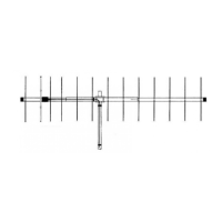
Your Cushcralt l7B2 Boomer antenna is designed and manufactured
to
giw
fouble lrss ssrvice. This anbnna will
perform
as sp€cified if the
instructions
and suggesùons in fris manual are followgd and care
is used in the assembly and installation. When checking
the components received
in
your
ântenna
pâckâge
use the
parts
listsd b€side each diagram. There
is a master
parts
list on
page
7. lf
you
are
unable to locate any tube
or
component, check the inside ol all tubing.
IMPORTANT: Save the weight
labellrcn
he outside ol the catton. Eæh antenna is webhed
atthe factoty
to verify the
pafts
count. ll
you
claim a missing
paft, you
will be asked lor the
weight
wrilicalon label.
PLANNING
Plan
your
installâtjon
carefully. lf
you
use volunteer helpers be sure
that they are
qualified
to
assist
you.
Maks csrlain that everyone
involved
underslands that
you
are
in
charge and
that they must follow
your
instructions. lf
you
have any doubts at all, employ a
professional
antenna
installation company
to install
your
antenna.
LOCATION
Location of the antenna is
very important.
Sunounding
objects such as trees,
power
lines, other antennas, etc. will seriously reducs efficiercy.
To
minimize the effr-.cts ot sunounding objects, mount the antenna
as high and in the clear as
possible.
lf metal
guy
wires are used,
they should bs
broken with strain insulators. EXTREME
CARE MUST BE USED FOR YOUR SAFETY. YOU MUST
INSURE
THAT WHILE THE
l7B2 lS lN
OPEMTION NEITHER PEOPLE
OR PETS CAN COME IN CONTACT WTH ANY PORTION
OF YOUR
ANTENNA, DEADLY VOLTAGES
AND
CURRENTS
IVAY
EXIST. ALSO,
SINCE THE EFFECTS OF EXPOSURE
TO
RF FIELDS
ARE NOT FULLY UNDERSTOOD,
LONG
TERM
EXPOSURE TO
INTENSE
RF FIELDS
IS NOT RECOMMENDED,
THEBE IS
A WARNING
SÏICKER WHICH
MUST BE ATTACHED
TO THE
BOOM
AS SHOWN IN FIGURE E.
MOUNTING
The mast
mounl bracket will accommodat€ up to a 2'
(5.1
cm) mast. A
I
-
1/2" OD
(3.S
cm) or larger heavy wall tubing
mast should bs used.
A
good
heaw duty
antenna rotâtor will
p.ovide
the best servics and longgst life.
Often it is desirable to mount several antennas
on one mast. To
keep
possible
interaction to a minimum,
place
your
antennas
as fâr apart as
you
can.
SYSTEM GROUNDING
Direct
grounding
of the antsnna, mast and tower is
very important. This serves as
protection
from lightning strikss and static buildup, and lrom high
vollage which is
present
in the
radio equipment
connected to the antenna.
A
good
electrical connection should be made
to one or mors
ground
rods
(or
other extensive
ground
sysùem) dir€ctly at the base ol
the tower or mast,
using
at least #10AWG
ground
wire and non-corrosive hardware.
For
details and safety standards, consult the National Electrical Code.
You should also use a coaxial lightning arrester. Cushcraft offers
several diltsrgnt
models, such as LAC-1, LAC-2 and he LAC-4
series
ASSEMBLY
Assemble
your
antenna by following the
direclions and illustrations
in steps 1
through 7. Atter
ihe antenna is
completely assembled, \,erify
dimensions and €lement spacings for accuracy. Then,
return to the section
below
for final tuning.
TUNING
PROCEDURE
The 1 782 does not normally requke tuning after assembly.
However, il
you
wish to check he VSWR betore installation,
please
obsen/€ the following
procedures.
To
prevent
detuning the antenna, it should be tuned in
place
or at least
7
feet
(2.13
meters)
above
ground
and clear ol surrounding
objects. Keep all meial obstructions
such as
guy
wires and other antennas
at least
10 feet
(3.05
m) away since they will nullily any âdjusùnent
and
degraded
performance
will result-
Run the coax cable from
your
transmittêr to the area in which the antenna
is
going
to be
tested. The length of lhis cable
or
your
leedline is not critical.
Connect a
good
quality
VHF VSWR bridge to the end of this cable.
Connect
a short
length
of
cable
[20
tt
(610
cm]
or lessl
from the VSWR
bridge to
the antenna. Set the trânsmitter to
your
center operating frequency.
When
you
read
VSWR,
be sure
you
move far enough
away from the antenna
so
that
your
body does not
etfect the
reading.
Measure ths VSWR. lf it is too high, move both
T-Maich strâps
(1
25) by 1/4'
(.6
cm) either inward or outward and check the VSWR.
Both T-ttatch
sùaps should be the same dislanæ lrcm lhe centet ol the d
ven
elemerL
lt the VSWR
improved, tren
continue moving
the T-Match skâps
in
the
same direction. lf the VSWR deteriorated
then move the T-Match strâps in the opposite direction. Repeat this
procedure
until no turther
improvement can be made. You have matched
your
antenna. Then
tighten all
connections
gn
the T-Match driven el€ment assembly.
Tape 6s
leedline to the boom and mast as shown in figure l.
 Loading...