EasyManua.ls Logo

CyberPower LX1500GU - User Manual

CyberPower LX1500GU
2 pages
Print Icon
To Next Page IconTo Next Page
Loading...
Yellow Wire to (+)Red Connector
Black Wire to (-)Black Connector
Red Wire to (+)Red Connector
Yellow Wire to (-)Black Connector
LX1100G / LX1325GU / LX1500GU
User’s Manual
K01-0000411-01
Thank you for purchasing a CyberPower product. Please take a few minutes to register your product at www.cpsww.com/registration.
Registration certifies your product's warranty, confirms your ownership in the event of a product loss or theft and entitles you to free technical
support. Register your product now to receive the benefits of CyberPower ownership.
(SAVE THESE INSTRUCTIONS)
This Manual Contains Important Instructions that should be followed during Installation and Maintenance of the UPS and batteries.
CAUTION! To prevent the risk of fire or electric shock, install in a temperature and humidity controlled indoor area free of conductive
contaminants. (Please see specifications for acceptable temperature and humidity range).
CAUTION! To reduce the risk of electric shock, do not remove the cover except to service the battery. Turn off and unplug the unit before
servicing the batteries. There are no user serviceable parts inside except for the battery.
CAUTION! Hazardous live parts inside can be energized by the battery even when the AC input power is disconnected.
CAUTION! The UPS must be connected to an AC power outlet with fuse or circuit breaker protection. Do not plug into an outlet that is not
grounded. If you need to de-energize this equipment, turn off and unplug the unit.
CAUTION! To avoid electric shock, turn off the unit and unplug it from the AC power source before servicing the battery.
CAUTION! To reduce the risk of fire, connect only to a circuit provided with 20 amperes maximum branch circuit over current protection in
accordance with the National Electric Code, ANSI/NFPA 70.
DO NOT USE FOR MEDICAL OR LIFE SUPPORT EQUIPMENT! CyberPower Systems does not sell products for life support or medical
applications. DO NOT use in any circumstance that would affect the operation and safety of life support equipment, medical applications, or
patient care.
DO NOT USE WITH OR NEAR AQUARIUMS! To reduce the risk of fire or electric shock, do not use with or near an aquarium. Condensation
from the aquarium can cause the unit to short out.
DO NOT USE THE UPS ON ANY TRANSPORTATION! To reduce the risk of fire or electric shock, do not use the unit on any transportation
such as airplanes or ships. The effect of shock or vibration caused during transit and the damp environment can cause the unit to short out.
INTRODUCTION
Thank you for selecting a CyberPower Systems UPS product. This UPS is designed to provide unsurpassed power protection, operation and
performance during the lifetime of the product.
UNPACKING
Inspect the UPS upon receipt. The box should contain the following:
(a) UPS (b) Users manual (c) USB A+B type cable (d) Function Setup Guide
*PowerPane Personal Edition software is available on our website. Please visit www.cpsww.com and go to the Software Section for
free download.
OVERVIEW
The LX1100G/LX1325GU/LX1500GU provides complete power protection from utility power that is not always consistent.
The LX1100G/LX1325GU/LX1500GU features 890 Joules of surge protection. The unit provides long lasting battery
backup during power outages with maintenance free batteries. The LX1100G/LX1325GU/LX1500GU ensures consistent
power to your computer system and includes software that will automatically save your open files and shutdown your
computer system during a utility power loss.
AUTOMATIC VOLTAGE REGULATOR
The LX1100G/LX1325GU/LX1500GU stabilizes inconsistent utility power voltage to nominal levels that are safe for equipment. Inconsistent
incoming utility power may be damaging to important data files and hardware, but with Automatic Voltage Regulation (AVR), damaging voltage
levels are corrected to safe levels. AVR automatically increases low utility power or decreases high utility power to a consistent and safe
110/120 volts.
HOW TO DETERMINE THE POWER REQUIREMENTS OF YOUR EQUIPMENT
1. Ensure that the equipment plugged into the outlet does not exceed the UPS’s rated capacity (1100VA/660W for LX1100G, 1325VA/810W for
LX1325GU, 1500VA/900W for LX1500GU). If the rated capacity of the unit is exceeded, an overload condition may occur and cause the
UPS to shut down or the circuit breaker to trip.
2. There are many factors that can affect the amount of power that your computer system will require. It is suggested that the load placed on
the battery outlets not exceed 80% of the units capacity.
HARDWARE INSTALLATION GUIDE
1. Your new UPS may be used immediately upon receipt. However, after receiving a new UPS, to ensure the
batterys maximum charge capacity, it is recommended that you charge the battery for at least 8 hours.
Your UPS is equipped with an auto-charge feature. When the UPS is plugged into an AC outlet, the
battery will automatically charge whether the UPS is turned on or off.
2. Note: This UPS is designed with a safety feature to keep the system from being turned on during shipment.
The first time you turn the UPS on, you will need to have it connected to AC power or it will not power up.
3. With the UPS unit turned off and unplugged, connect your computer, monitor, and any other peripherals requiring battery backup into the
battery power supplied outlets. DO NOT plug a laser printer, paper shredder, copier, space heater, vacuum, sump pump or other large
electrical devices into the Battery and Surge Protected Outlets. The power demands of these devices may overload and damage
the UPS.
4. To protect a fax, phone or modem, connect a telephone cable or network cable from the wall jack outlet to the IN
jack of the UPS. Connect a telephone cable or network cable from the OUT jack of the UPS to a fax machine,
telephone, modem, or network devices.
5. Plug the UPS into a 2 pole, 3 wire grounded receptacle (wall outlet). Make sure the wall branch outlet is
protected by a fuse or circuit breaker and does not service equipment with large electrical demands (e.g. air
conditioner, copier, etc…). The warranty prohibits the use of extension cords, outlet strips, and surge strips.
6. Press the power switch to turn the unit on. The Power On indicator light will illuminate and the unit will beep.
If an overload is detected, an audible alarm will sound and the unit will emit one long beep. To correct this, turn the UPS off and unplug at
least one piece of equipment from the battery power supplied outlets. Make sure the circuit breaker is depressed and then turn the UPS on.
7. To maintain optimal battery charge, leave the UPS plugged into an AC outlet at all times.
8. To store the UPS for an extended period, cover it and store with the battery fully charged. While in storage, recharge the battery every three
months to ensure battery life.
9. Ensure the wall outlet and UPS are located near the equipment being attached for proper accessibility.
DESCRIPTION
1 Power Switch
Used as the master on/off switch for equipment connected to the battery power supplied outlets. (Please refer to the Function Setup Guide
for more information.)
2 Power On Indicator
This LED is illuminated when the utility power is normal and the UPS outlets are providing power, free of surges and spikes.
3 LCD module display
The LCD display shows all the UPS information using icons and messages. For more information please review the Definitions for
Illuminated LCD Indicators section below.
4 LCD Display Toggle/Selected Switch
The switch can be used to select the LCD display contents including Input Voltage, Output Voltage, and Estimated Run Time. The toggle
frequency is set to one time per second.
5 USB Charging Ports (except for LX1100G)
The USB Charging ports provide 5V 2.1A power output.
6 Battery and Surge Protected Outlets
The UPS has five battery powered/surge suppression outlets for connected equipment to ensure temporary uninterrupted operation of your
equipment during a power failure. (DO NOT plug a laser printer, paper shredder, copier, space heater, vacuum, sump pump or other
large electrical devices into the Battery and Surge Protected Outlets. The power demands of these devices may overload and
damage the unit.)
7 Full-Time Surge Protection Outlets
The UPS has five surge suppression outlets.
8 Circuit Breaker
Located on the back of the UPS, the circuit breaker serves to provide overload and fault protection.
9 USB Ports to PC
The USB port allows connection and communication between the USB port on the computer and the UPS unit.
10 Communication Protection Ports
Communication protection ports will protect any standard modem, fax, telephone line, network or Ethernet connection (RJ11/RJ45).
11 Wiring Fault Indicator (red)
This LED indicator will illuminate to warn the user that a wiring problem exists, such as bad ground, missing ground or reversed wiring. If
this is illuminated, disconnect all electrical equipment from the outlet and have an electrician verify the outlet is properly wired. The UPS will
not provide surge protection without being plugged into a grounded and properly wired wall outlet.
12 Coax/Cable/DSS Surge Protection
The Coax/Cable/DSS protection ports will protect any cable modem, CATV converter, or DSS receiver.
13 Outlets Designed for AC Adapters
The unit has two outlets spaced to allow AC power adapter blocks to be plugged into the UPS without blocking adjacent outlets.
REPLACING THE BATTERY
Replacement of batteries located in an OPERATOR ACCESS AREA.
1. When replacing batteries, replace with the same number of the following battery: CyberPower / RB1270X2C for the LX1100G /
LX1325GU, and CyberPower / RB1290X2 for the LX1500GU.
2. CAUTION! Risk of Energy Hazard, 24 V, maximum 9 Ampere-hour battery. Before replacing batteries, remove conductive jewelry such
as chains, wrist watches, and rings. High energy conducted through these materials could cause severe burns.
3. CAUTION! Do not dispose of batteries in a fire. The batteries may explode.
4. CAUTION! Do not open or mutilate batteries. Released material is harmful to the skin and eyes. It may be toxic.
5. CAUTION: A battery can present a risk of electrical shock and high short circuit current. The following precautions should be observed
when working on batteries:
1) Remove watches rings, or other metal objects.
2) Use tools with insulated handles.
CAUTION - RISK OF EXPLOSION IF BATTERY IS REPLACED BY AN INCORRECT TYPE. DISPOSE OF USED BATTERIES ACCORDING
TO LOCAL REGULATIONS.
BATTERY REPLACEMENT PROCEDURE:
1. Turn off and unplug all connected equipment.
2. Turn the UPS off and unplug it from the AC power source.
3. Turn the UPS on its side.
4. Remove two retaining screws located on the bottom of the UPS.
5. Slide the battery compartment cover completely off of the unit.
6. Remove the battery which is located on the right side from the compartment.
7. Disconnect the battery wires from the right side of the battery.
8. Slide the remaining battery from left to right and remove it from the compartment.
9. Disconnect the battery wires from the remaining battery.
10. Install the "left side" replacement battery by connecting the yellow wire (+) to the red connector from the battery and the black wire (-) to
the black connector from the battery. Place the battery into the left side of the compartment.
11. Install the "right side" replacement battery by connecting the red wire (+) to the red connector from the battery and yellow wire (-) to the
black connector from the battery. Place the battery into the right side of the compartment. Note: Only new batteries should be used for
replacement and both batteries should be replaced at the same time to insure maximum life span.
12. Slide back the battery compartment cover and tighten the retaining screws.
13. Recharge the UPS for 8-16 hours to fully charge the battery.
REMINDER: Batteries are considered HAZARDOUS WASTE and must be disposed of properly. Most retailers that sell lead-acid batteries
collect used batteries for recycling, as required by local regulations.
1. INPUT voltage meter:
This meter measures the AC voltage that the UPS system is receiving from the utility wall outlet. The UPS is designed, through the use of
automatic voltage regulation, to continuously correct output voltage to connected equipment to a safe 110/120 voltage output range. In the
event of a complete power loss, severe brownout, or over-voltage, the UPS relies on its internal battery to supply consistent 110/120
output voltage. The INPUT voltage meter can be used as a diagnostic tool to identify poor-quality input power.
2. OUTPUT voltage meter:
This meter measures, in real time, the AC voltage that the UPS system is providing to the computer, such as normal line mode, AVR mode,
and battery backup mode. (Note: The OUTPUT voltage meter shows the status of the battery backup outlets.)
3. ESTIMATED RUNTIME:
This displays the run time estimate of the UPS with current battery capacity and load.
4. NORMAL icon:
This icon appears when the UPS is working under normal conditions.
5. BATTERY icon:
During a severe brownout or blackout, this icon appears and an alarm sounds (two short beeps followed by a pause) to indicate the UPS is
operating from its internal batteries. During a prolonged brownout or blackout, the alarm will sound continuously to indicate the UPSs
batteries are nearly out of power. You should save files and turn off your equipment immediately or allow the software to shut the system
down.
6. AVR (Automatic Voltage Regulation) icon:
This icon appears whenever your UPS is automatically correcting low AC line voltage without using battery power. This is a normal,
BASIC OPERATION
INSTALLING YOUR UPS SYSTEM
IMPORTANT SAFETY INSTRUCTIONS
DEFINITIONS FOR ILLUMINATED LCD INDICATORS
PRODUCT REGISTRATION
All manuals and user guides at all-guides.com
Question and Answer IconNeed help?

Do you have a question about the CyberPower LX1500GU and is the answer not in the manual?

Summary

Important Safety Instructions

General Safety Precautions

Key safety warnings regarding installation, handling, and environmental conditions for the UPS.

Specific Use Restrictions

Prohibitions on using the UPS with medical, aquarium, or transport applications to prevent hazards.

Product Overview and Features

Unpacking and Initial Setup

Steps for unpacking the UPS unit and recommended initial battery charging.

Automatic Voltage Regulation (AVR)

Explanation of how AVR stabilizes voltage for equipment protection against fluctuations.

Installation and Hardware Guide

Determining Equipment Power Needs

Guidance on calculating equipment load to avoid UPS overload conditions.

UPS Hardware Installation Steps

Step-by-step instructions for connecting peripherals and the UPS to power sources.

Basic Operation and Indicators

Power Switch Function

Description of the main power switch for controlling connected equipment.

Understanding LCD Indicators

Explanation of icons and meters on the LCD display for UPS status monitoring.

Troubleshooting

Common Problems and Solutions

Table detailing common UPS issues, their causes, and recommended solutions.

Technical Specifications

Model Specifications Comparison

Comparison table of key technical specifications for different UPS models.

Safety Approvals

List of safety certifications and standards the UPS unit complies with.

System Block Diagram

CyberPower GreenPath Technology

Overview

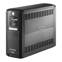
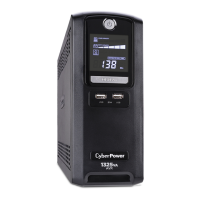
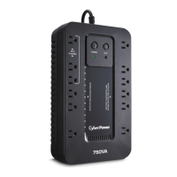
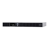
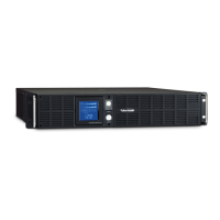
This document describes a CyberPower Uninterruptible Power Supply (UPS) system, specifically models LX1100G, LX1325GU, and LX1500GU, designed to provide power protection and backup for electronic devices.

Function Description

The primary function of this UPS system is to provide continuous power to connected electronic devices, protecting them from power outages, surges, and sags. It features Automatic Voltage Regulation (AVR), which stabilizes incoming utility power without relying on battery power, thereby conserving battery life for actual power outages. The UPS includes both battery backup and surge-protected outlets, ensuring that critical devices remain operational during power disruptions while less critical devices are protected from surges.

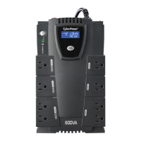
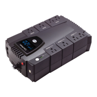
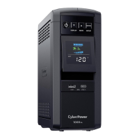
The system is equipped with a multi-function LCD display that provides real-time information about the UPS status, including input voltage, output voltage, estimated runtime, and battery capacity. This display allows users to monitor the power conditions and the UPS's performance at a glance. The UPS also supports a "GreenPower UPS™ Technology" with a patented bypass design, which significantly reduces energy consumption by bypassing the transformer when utility power is normal, leading to increased power efficiency and reduced heat generation.

For enhanced control and monitoring, the UPS can be connected to a computer via a USB port and managed using CyberPower's PowerPanel® Personal Edition software. This software enables users to monitor the UPS status, configure settings, schedule shutdowns, and receive alerts, providing comprehensive power management capabilities. The UPS also includes USB charging ports, allowing users to charge mobile devices directly from the unit.

Usage Features

The UPS is designed for straightforward installation and operation. Before initial use, it is recommended to fully charge the battery by plugging the unit into an AC outlet for at least 8 hours. The unit should be placed in a controlled environment, away from excessive moisture, heat, or dust, and should not be used with aquariums or medical/life support devices.

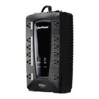
Connecting equipment to the UPS is simple: critical devices requiring battery backup should be plugged into the "Battery Backup & Surge Protected Outlets," while less critical devices needing only surge protection can be connected to the "Full-Time Surge Protection Outlets." It is important not to overload the UPS by exceeding its VA capacity, as this can trigger an overload alarm and potentially trip the circuit breaker. Laser printers, shredders, copiers, space heaters, and other high-power devices should generally be plugged into surge-only outlets or directly into a wall outlet, not the battery backup outlets, to avoid overloading the unit.

The LCD display provides various indicators and alarms to keep users informed. It shows the input voltage from the utility, the output voltage supplied to connected equipment, and the estimated runtime remaining on battery power. Icons on the display indicate different operational modes, such as normal mode, AVR mode, battery mode, and silent mode. Audible alarms alert users to critical events like power outages, low battery, or overload conditions. The silent mode feature allows users to disable audible alarms for a period, which can be useful in quiet environments.

The PowerPanel® Personal Edition software offers advanced usage features. Users can customize settings such as shutdown schedules, alarm thresholds, and power management options. It can perform automatic shutdowns of connected computers during extended power outages, ensuring data integrity. The software also logs power events, providing a historical record of power fluctuations and UPS performance.

Maintenance Features

The UPS is designed for minimal maintenance, but certain actions are recommended to ensure its longevity and optimal performance. The internal battery is a sealed, maintenance-free lead-acid battery, but it has a finite lifespan, typically 3 to 6 years, depending on the number of discharge/recharge cycles. When the battery is worn out, the UPS will indicate this, and it should be replaced by a CyberPower certified technician or by following the instructions provided by CyberPower Systems.

If the circuit breaker trips due to an overload, users can reset it by unplugging some equipment, waiting 10 seconds, and then depressing the circuit breaker button before turning the UPS back on. Regular monitoring of the battery capacity meter on the LCD display helps users understand the battery's charge level and anticipate when a replacement might be needed.

The troubleshooting section of the manual provides guidance for common issues, such as the UPS not performing expected runtime, not turning on, or the PowerPanel® software being inactive. These sections offer simple solutions like recharging the battery, checking connections, or contacting CyberPower Systems for more complex problems.

CyberPower encourages environmentally sound methods for disposal and recycling of its UPS products and batteries, in accordance with local regulations. This commitment to environmental responsibility is part of the "GreenPower UPS™ Technology" philosophy.

The product comes with a Limited Warranty and Connected Equipment Guarantee, covering defects in materials and workmanship for three years and connected equipment for as long as the original purchaser owns the product. This warranty also outlines procedures for obtaining service and making claims for connected equipment damage, emphasizing the importance of proper installation and usage within the product's specified limits.

CyberPower LX1500GU Specifications

General IconGeneral
Waveform-
Output power900 W
UPS topologyLine-Interactive
Input frequency60 Hz
Maximum current12 A
Surge energy rating890 J
Output power capacity1.5 kVA
Output voltage regulation5 %
Input operation voltage (max)139 V
Input operation voltage (min)91 V
Output operation voltage (max)120 V
Output operation voltage (min)- V
Automatic Voltage Regulation (AVR)Yes
AC outlet typesNEMA 5–15R
AC outlets quantity10 AC outlet(s)
Operating altitude0 - 15000 m
Storage temperature (T-T)-15 - 45 °C
Operating temperature (T-T)0 - 40 °C
Operating relative humidity (H-H)0 - 95 %
Sustainability certificatesRoHS, ENERGY STAR
Form factorTower
Cable length1.83 m
Display typeLCD
CertificationFCC Clase B, UL
Product colorBlack
Weight and Dimensions IconWeight and Dimensions
Depth249 mm
Width99 mm
Height348 mm
Weight11300 g

Related product manuals