©2019 Cyber Power Systems (USA), Inc. All rights reserved. All other trademarks are the property of their respective owners.
8
Check wiring dimensions with the following table.
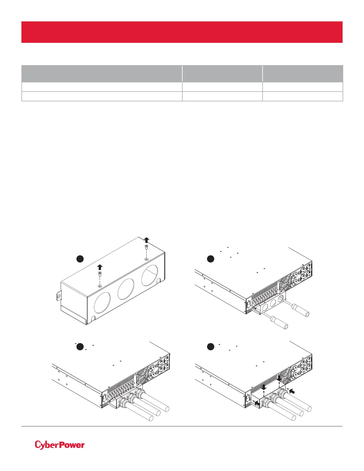
HARDWIRING THE INPUT/OUTPUT TERMINALS
Step 1: Separate the terminal block cover
Loosen the two screws joining the top and bottom terminal block covers to separate them.
Step 2: Secure the bottom cover on to the step-down transformer
Tighten the two screws to secure the bottom cover on to the step-down transformer terminal block.
Step 3: Input/Output configuration
Insert the input/output cables through the appropriate cable gland. Hardwire the input/output wiring to
their respective terminals as shown in the terminal block identification and configuration table.
Step 4: Secure the top cover
Use four screws to secure the top terminal block cover on to the step-down transformer.
STEP-DOWN AND ISOLATION TRANSFORMERS
WITH HARDWIRE INPUT TERMINAL BLOCK
WIRING AWG WIRING mm
2
OL6KSTF 10 AWG 5.5 mm
2
OL10KSTF 6 AWG 14.0 mm
2
ELECTRICAL INSTALLATION
4
1 2
3
 Loading...