Assembly and Setup
Page 2–5
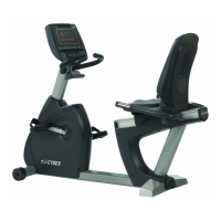
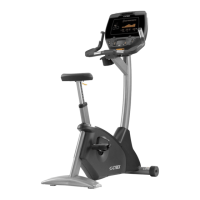
Cybex 750C/750R Owner’s Manual
D. Carefully lower the rear foot so unit is in intended
location.
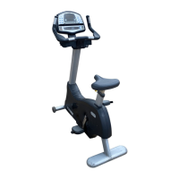
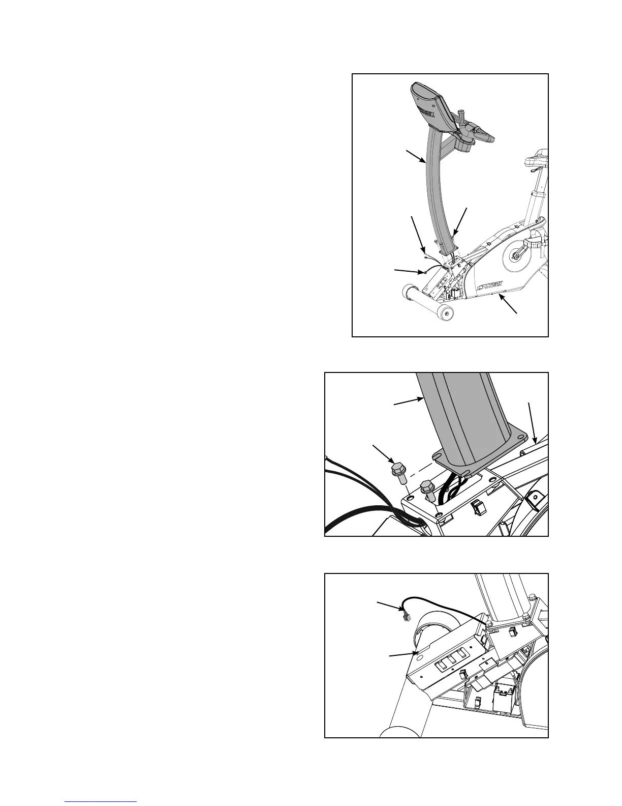
3. Attach the console assembly to base assembly.
NOTE: If installing the A/V option, refer to the 750C A/V
bracket installation instructions (supplied with the
A/V bracket).
A. Locate the console assembly (#2) and four
mounting screws 5/16-18 x .75” (#11). See
Figure 2.
B. Hand thread two mounting screws 5/16-18 x .75”
(#11) into the base assembly. See Figure 3.
NOTE: The console assembly (#2) will need to be
supported during steps 3C to 3F.
C. Carefully feed the display cable and optional A/V
cable through the frame as shown in Figure 2.
NOTE: Do not pinch or damage the cables during
assembly.
D. Place the console assembly (#2) in the
correct position on the base assembly (#1)
by sliding into position onto the two
mounting screws 5/16-18 x .75” (#11). See
Figure 3.
E. Hand thread the other two screws 5/16-18 x
.75” (#11). See Figure 2.
F. Securely fasten the four screws 5/16-18 x
.75” (#11) with a 1/2” socket wrench.
G. Plug the display cable into the display
cable connector on the lower control
board. See Figure 4.
NOTE: Ensure the cable connector is securely
fastened.
#11
#1
#1
Figure 2
#2
Figure 3
Figure 4
Display
Cable
Connector
Display
Cable
Display
Cable
Optional
A/V Cable
#11
#2
 Loading...