Do you have a question about the CZone Signal Interface and is the answer not in the manual?
Provides guidance for safe and effective operation, maintenance, and troubleshooting of the Signal Interface Module (SI).
Details the manufacturer's guarantee based on adherence to guidelines and specifications, and conditions for invalidation.
States that all units are tested and inspected during production, with a standard two-year guarantee period.
Confirms that manual specifications apply only to standard versions of the Signal Interface (SI) delivered by BEP Marine.
States BEP Marine accepts no liability for consequential damage or errors in manuals, with a caution about identification labels.
Specifies that changes to the Signal Interface require written permission from BEP.
Explains pictograms used for CAUTION, WARNING, and general attention points in the manual.
Defines correct usage conditions and warns against use in explosive or flammable environments.
Requires users to have access to and be familiar with the user's manual.
Outlines safety measures for maintenance, including switching off supply and using original spare parts.
Covers connection standards, working with power sources, and regular wiring checks.
Explains the Signal Interface (SI) connects CZone system to sensors, alarms, and switching devices for automated operation.
Lists key features like input types, LED indicators, dimensions, IPX5 rating, and NMEA2000 output.
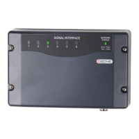
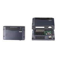
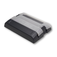
Identifies the physical components of the Signal Interface unit using a labeled diagram.
Provides installation guidelines for vertical mounting, seals, cable glands, and labels to maintain IPX5 rating.
Details DC negative connection, signal input connections (1-6), NMEA2000 connection, and power source requirements.
Explains how to set the dipswitch for unique module configuration on the CZone network.
Guides through checking connections, powering up the network, verifying LEDs, and testing inputs/outputs.
Details the meaning of different LED colors and flash patterns for circuit status indication.
Explains the LED indicators for network power status and network traffic.
Describes the label inside the unit showing LED codes and electrical connections to the unit.
Explains labels for module identification and dipswitch settings to prevent cover swapping.
Lists the available module part numbers with and without seals and connectors.
Lists part numbers for accessories like cable glands and terminal blocks.
| Analog Inputs | 4 |
|---|---|
| Current Consumption | 100mA @ 12V |
| Humidity | 95% RH non-condensing |
| Signal Type | Digital/Analog |
| Connector Type | Screw Terminal |