EN / CZone® Signal Interface (SI) User & Installation Manual
5 Installation
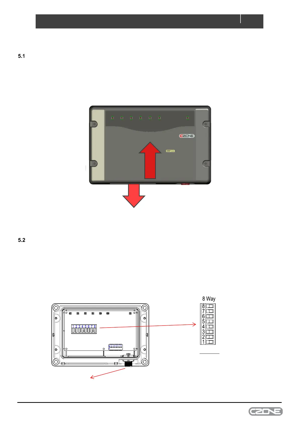
GUIDELINES
• Ensure the modules are installed vertically with the cables exiting downwards, this ensures IPX5 rating is
retained.
• All seals and cable glands must be fitted including blanking plugs inserted in any unused positions.
• Ensure all labels are fitted and correct
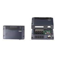
CONNECTIONS
• Connect DC Neg to SI input 8, used as reference to ground.
• Connect each input to SI, inputs 1-6. Input 7 is not connected.
• Connect an NMEA2000 drop cable from the SI to the NMEA2000 backbone.
• Ensure NMEA2000 network is properly terminated and connected to 12V power source.
Figure 3. Connections
No connection
DC Negative
Signal input 1
Signal input 2
Signal input 3
Signal input 4
Signal input 5
Signal input 6
Signal inputs:
10-180 Ohm Sender
240-33 Ohm Sender
0-5v Sender
Negative (for switching purposes)
Positive (0-32v, for switching purposes )
Figure 2. Mounting