Do you have a question about the CZone COI and is the answer not in the manual?
Guideline for safe and effective operation, maintenance, and minor malfunction correction of the Combination Output Interface.
BEP Marine guarantees unit built to applicable standards. Warranty may be voided by non-compliance with manual instructions.
Units are extensively tested prior to delivery. Standard guarantee period is two years.
Manual applies solely to standard versions of the Combined Output Interface delivered by BEP Marine.
BEP Marine accepts no liability for consequential damage or errors in the manual. Never remove the identification label.
Changes to the COI may only be carried out after obtaining written permission from BEP.
Safety instructions and warnings are marked with pictograms like CAUTION, WARNING, and general attention symbols.
Use the COI only in technically correct conditions, protected from elements, and following manual instructions. Avoid hazardous environments.
The user must always have access to and be familiar with the user's manual.
Switch off supply before maintenance. Use only original spare parts. Ensure third parties cannot reverse measures.
Ensure connections comply with local standards. Only qualified electricians should work on the system. Check wiring annually.
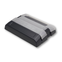
Combines multiple input/output devices into one module, offering high density, IPX5 protection, and Deutsch connectors.
High density 30-channel module, mechanical fuse protection, IPX5 rating, NMEA 2000 certification, and USB update capability.
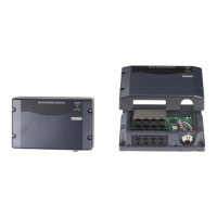
Diagrams and labels identifying key components of the COI module, including connectors, LEDs, and controls.
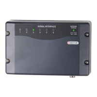
Details the meaning of various LED indicators for circuit status, power, and network connectivity.
Guidance on labeling circuit names on the blank label panel for identification and configuration.
Covers USB drive requirements, reading configuration, writing configuration, and updating device firmware.
Illustrates a typical CZone COI and Masterbus system setup, showing connections and components.
Lists necessary items for installation, including the COI module, connector kits, tools, fuses, and wiring.
Stipulations for COI placement: accessibility, visibility of LEDs, distance from high-current conductors, and mounting strength.
Guidance on planning inputs/outputs, understanding output channel ratings, and wiring strategies for specific functions like Bilge Pumps.
Lists parts included in the Deutsch connector kit, detailing part numbers, descriptions, and quantities.
Instructions for mounting the COI, including locating screw points and securing it to a flat surface.
Steps to connect high-current cables using Deutsch contacts, ensuring proper pin insertion and sealing.
Steps to connect low-current cables using Deutsch contacts, ensuring proper pin insertion and sealing.
Procedure for connecting analogue inputs, including switch or sensor connections and NMEA 2000 conversion.
Instructions for connecting the COI to an NMEA2000 backbone, ensuring proper termination and power.
How to connect digital switches using the optional breakout, ensuring IPX5 rating with blanking caps.
Connect the DC negative cable from the battery terminal or negative bus to the COI's M6 negative stud.
Connect the DC positive cable, ensuring it's appropriately sized, fused, and protected for the total load.
Instructions for writing circuit names on labels and inserting appropriately rated fuses into the correct fuse holder positions.
Instructions on setting the dipswitch on the COI, emphasizing uniqueness for network functionality and configuration matching.
Steps for initial power-up, including checking connections, powering the NMEA2000 network, and verifying LEDs.
Lists electrical, physical, and performance specifications including output channels, inputs, power, and protection.
Details NMEA 2000 Parameter Group Numbers (PGNs) sent from the COI, including description and fields.
Diagrams showing the physical dimensions of the COI module with and without covers.
Lists part numbers and descriptions for the COI module and related accessories like connectors, cables, and switches.
Declaration that the CZone COI C/W Connectors and COI No Connectors conform to specified standards.
Lists the standards, including EMC: EN 60945:2002 and FCC 47 CFR Part 15, to which the products conform.
| Brand | CZone |
|---|---|
| Model | COI |
| Category | Recording Equipment |
| Language | English |