LABELLING 3.5
The unit is supplied with a blank label panel. The circuit names can be hand-written on this with a marker pen to
indicate the circuit name.
Custom polycarbonate labels may be ordered from BEP Marine for a professional looking solution.
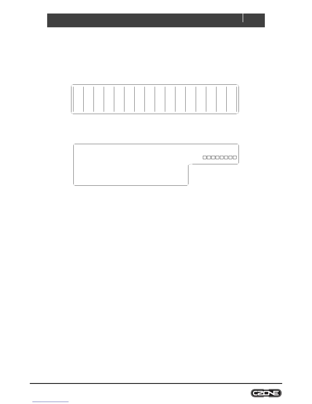
Figure 4. Blank Circuit Label
Figure 5. Blank Input Label
USB PORT 3.6
The USB port on the COI allows system software updates and configuration files to be loaded from a USB Memory
Stick. This feature is only supported on devices with firmware version 6.11.30.0 or newer.
3.6.1 General Requirements & Tips
Make sure the USB drive is FAT32 formatted.
USB drive sizes up to 32GB are recommended.
Most USB brands have been verified up to 32GB in size, including Strontium, Sandisk, Toshiba, Verbatim,
Kingston, Samsung, Apacer etc.
For USB drives 64GB and above only a limited number of devices from Kingston have been verified for
operation.
It is best, but not necessary, to use an empty USB drive for these operations.
3.6.2 Reading Configuration From Network
To read the existing configuration from the network to the USB drive you must:
1. Insert a USB drive with NO existing (*.zcf or *.czfwp) files in the root folder.
2. Press the USB button for 5sec or until the LED flashes RED.
3. Wait for the USB LED to turn solid green before removing it. This should take less than 20sec. Once done it
will create/update 4 files:
a) *.zcf - The configuration file read from the network
b) *.csv - A spreadsheet listing information about the system and modules connected to the network
c) CZone.bak - A backup copy of the configuration file. This needs to be present when writing updated
configuration back to the network
d) CZone USB Result.txt – A text file describing the result of the last operation performed, as well as these
instructions
Analogue Inputs (IN-A)
1 _________________________
2 _________________________
3 _________________________
4 _________________________
5 _________________________
6 _________________________
7 _________________________
8 _________________________
Digital Switch Inputs (IN-D)
1 _____________________
2 _____________________
3 _____________________
4 _____________________
5 _____________________
6 _____________________
1
DIP
COI
2 3
4 5
6
7
8
__________________