LABELS & FUSES 4.7
1. Label the Circuits
1. Using a marker pen, write the output names (1-16) on the supplied label matching the load list and
physical plug connections.
2. Label the Inputs
1. Using a marker pen, write the analogue and digital input names matching the input list and physical plug
connections.
2. Write the COI module number and location (i.e. COI01 – Engine Room). This should match the module
name in the configuration.
3. Mark the dipswitch setting of the COI. This is usually assigned automatically when writing the
configuration and needs to be unique for each module on the CZone system.
INSERT FUSES 4.8
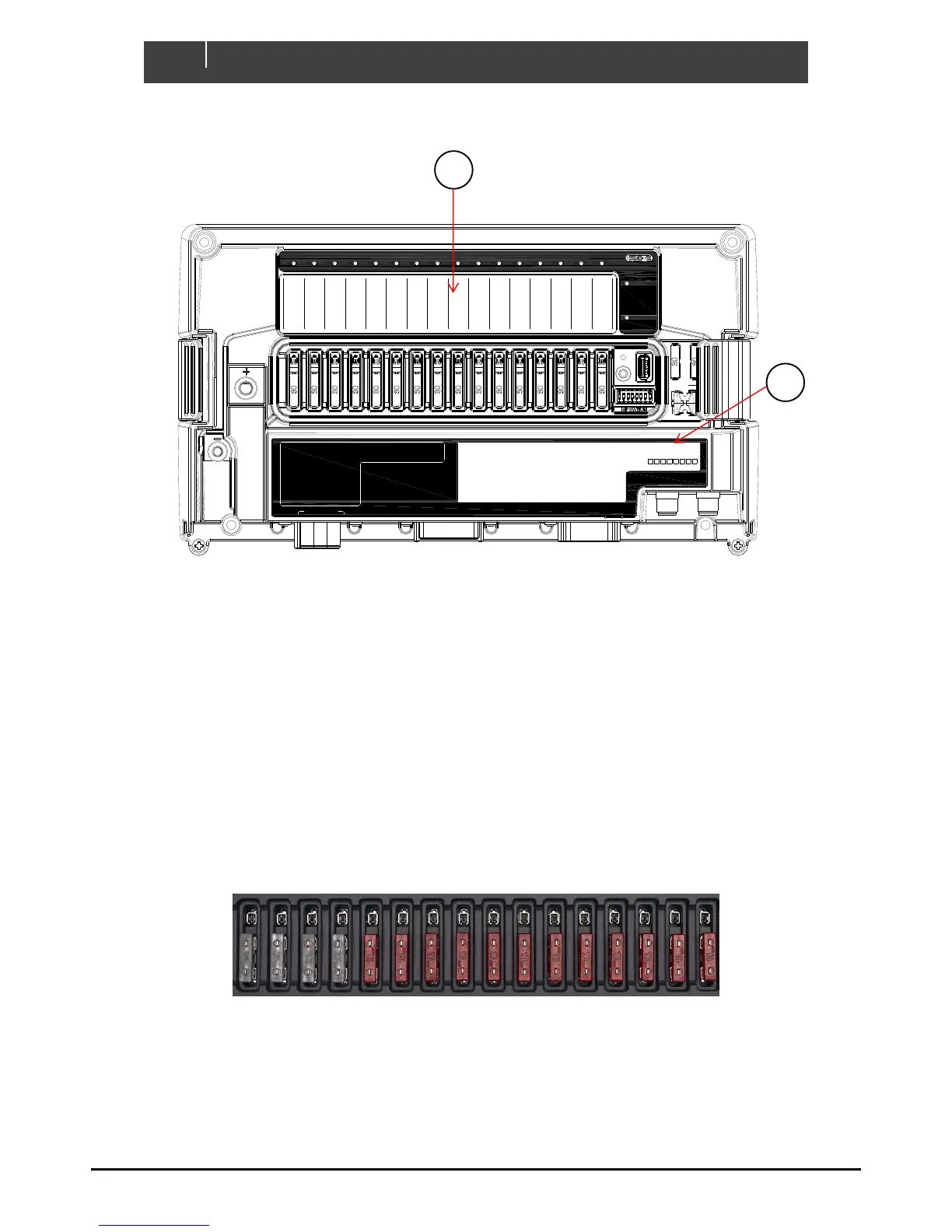
Figure 14. Fuses In Normal Operation
1. Insert appropriately rated ATC fuses into the NORMAL operation (bottom) position of all fuse holders.
2. The ATC fuse should be rated one size above the software fuse rating
1 2 3 4 5 6 7 8 9 10 11 12 13 14 15 16
Green - Power
Red Flash - Traffic
NETWORK
STATUS
Green - Available
Red - Low Volts
COI
POWER
Manual Fuse Bypass
Warning! Inserting
fuse creates ignition
hazard, ensure area is
free of explosive
gases
BYPASS
NORMAL
FUSE
NMEA
IN-D
OUT-L (5-16) IN-A (1-8)
Analogue Inputs (IN-A)
1 _________________________
2 _________________________
3 _________________________
4 _________________________
5 _________________________
6 _________________________
7 _________________________
8 _________________________
Digital Switch Inputs (IN-D)
1 _____________________
2 _____________________
3 _____________________
4 _____________________
5 _____________________
6 _____________________
1
DIP
COI
2 3 4 5 6 7 8
__________________
Channel LED Status Codes
GRN solid on = Channel on
1 x RED = Module not configured
2 x RED = Configuration conflict
3 x RED = Dip switch conflict
4 x RED = Memory failure
5 x RED = No modules detected
6 x RED = Low run current
7 x RED = Over current
8 x RED = Short circuit
9 x RED = Missing commander
10 x RED = Over temperature
11 x RED = Reverse current
12 x RED = Current calibration
OUT-H (1-4)